TPC6000
‐
A101
User
Manual
22
Step
6:
Insert
the
four
monitor
mounting
screws
provided
in
the
wall
mounting
kit
into
the
four
screw
holes
on
the
real
panel
of
the
flat
panel
PC
and
tighten
until
the
screw
shank
is
secured
against
the
rear
panel
Step
7:
Align
the
mounting
screws
on
the
monitor
rear
panel
with
the
mounting
holes
on
the
bracket.
Step
8:
Carefully
insert
the
screws
through
the
holes
and
gently
pull
the
monitor
downwards
until
the
monitor
rests
securely
in
the
slotted
holes.
And
ensure
that
all
four
of
the
mounting
screws
fit
snuggly
into
their
respective
slotted
holes.
Step
9:
Secure
the
panel
PC
by
fastening
the
retention
screw
of
the
wall
‐
mounting
bracket.
2.6.4
Panel
mounting
To
mount
the
TPC6000
‐
A101
flat
panel
PC
into
a
panel
(not
standard
attached),
please
follow
the
steps
below:
Step1:
Select
the
location
on
the
panel
to
mount
the
flat
panel
PC.
Step
2:
Cut
out
a
section
from
the
panel
that
corresponds
to
the
rear
panel
dimensions
of
the
flat
panel
PC.
Take
care
that
the
panel
section
that
is
cut
out
is
smaller
than
the
overall
size
of
the
metal
frame
that
surrounds
the
flat
panel
PC
but
just
large
enough
for
the
rear
panel
of
the
flat
panel
PC
to
fit
through.
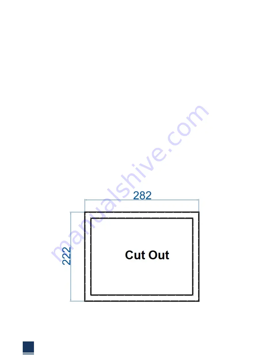
Recommended
cutout
size
as
shown
below:
Figure
2
‐
10:
TPC6000
‐
A101
cut
out.
Step
3:
Slide
the
flat
panel
PC
through
the
hole
until
the
frame
is
flush
against
the
panel.
Summary of Contents for TPC6000-A101
Page 1: ...TPC6000 A101 User Manual 1 User ManualVer1 0 TPC6000 A101 Robust Industrial Panel PC...
Page 8: ...TPC6000 A101 User Manual 8 Chapter 1 OVERVIEW...
Page 14: ...TPC6000 A101 User Manual 14 1 6 Dimensions Figure 1 5 TPC6000 A101 dimensions...
Page 15: ...TPC6000 A101 User Manual 15 Chapter 2 INSTALLATIONS...
Page 34: ...TPC6000 A101 User Manual 34 Press NEXT to continue...
Page 39: ...TPC6000 A101 User Manual 39 Press YES to agree the License agreement then go to the next step...
Page 41: ...TPC6000 A101 User Manual 41 Press YES to continue...
Page 44: ...TPC6000 A101 User Manual 44 Press NEXT to continue...
Page 46: ...TPC6000 A101 User Manual 46...
Page 49: ...TPC6000 A101 User Manual 49 Press NEXT to continue Press INSTALL to continue...
Page 55: ...TPC6000 A101 User Manual 55 Chapter 3 BIOS Setup...
Page 60: ...TPC6000 A101 User Manual 60 Figure 3 3 1PCI Subsystem Configuration Setting...
Page 61: ...TPC6000 A101 User Manual 61 3 3 2 ACPI Setting Figure 3 3 2ACPI Configuration Setting...
Page 64: ...TPC6000 A101 User Manual 64 3 3 5 USB Configuration Figure 3 3 5USB Configuration...
Page 66: ...TPC6000 A101 User Manual 66 3 3 7 PC Health Status Figure 3 3 7 PC Health status...
Page 67: ...TPC6000 A101 User Manual 67 3 3 8 PPM Configuration Figure 3 3 8 PPM Configuration...
Page 68: ...TPC6000 A101 User Manual 68 3 4 Chipset Settings hostbridge Figure 3 4 Chipset Settings...
Page 69: ...TPC6000 A101 User Manual 69 3 4 1 Intel graphic configuration...
Page 71: ...TPC6000 A101 User Manual 71 3 5 Chipset settings south bridge Figure 3 5 Chipset Settings...
Page 73: ...TPC6000 A101 User Manual 73 3 5 2 Power on configuration Figure 3 5 3Power on Settings...
Page 75: ...TPC6000 A101 User Manual 75 Figure 3 5 3 Boot configuration...
Page 76: ...TPC6000 A101 User Manual 76 3 6 Security settings Figure 3 6 Security settings...
Page 79: ...TPC6000 A101 User Manual 79 Chapter 4 System Maintenance...
Page 81: ...TPC6000 A101 User Manual 81 A Safety Precautions...
Page 85: ...TPC6000 A101 User Manual 85 B ALC662 Digital Microphone Configuration...
Page 90: ...TPC6000 A101 User Manual 90 C Watchdog Timer...
Page 93: ...TPC6000 A101 User Manual 93 D Hazardous Materials Disclosure...
Page 96: ...TPC6000 A101 User Manual 96 Chapter 5 Appendix A...


