TPC6000
‐
A101
User
Manual
19
Figure
2
‐
4:
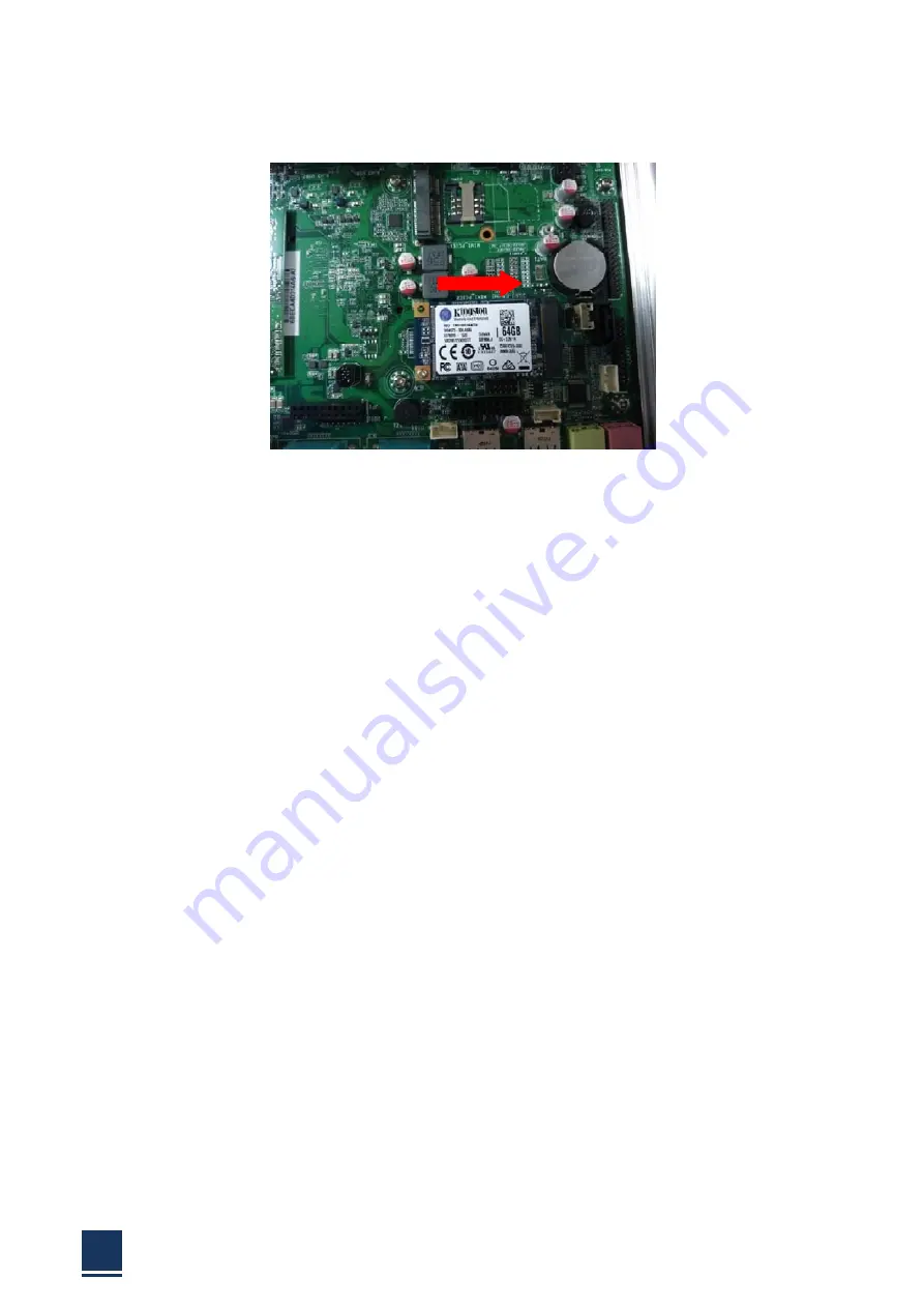
mSATA
SSD
installation
Step
3:
Replace
the
HDD
bracket,
cover
and
screws.
2.5
Memory
installation
This
section
outlines
the
installation
of
the
memory
in
the
TPC6000
‐
A101.
To
install
the
memory,
please
follow
the
steps
below:
Step1:
Flip
over
this
device
and
you
can
see
its
back.
Step
2:
Unfasten
the
4
silver
retention
screws
on
the
left
and
right
side.
(Figure
2
‐
5)
Step
4:
Lift
the
cover
to
remove.
Step
5:
Locate
the
memory
bracket.
Step
6:
Plug
the
DDR3L
memory
bar
into
the
DDR3L
slot
in
the
angle
of
45
degrees
then
push
lightly
down
till
the
two
metal
clips
vise
the
memory
bar
with
a
sound
“pa”,
and
done
safety.
Step
7:
Plant
the
cover
on
back
of
the
device.
2.6
Mounting
system
Warning:
The
panel
PC
is
very
heavy,
two
or
more
people
should
mount
the
panel
PC.
Dropping
or
bumping
the
panel
PC
during
installation
can
cause
serious
or
irreparable
damage
to
the
panel
PC
The
following
installation
options
are
available:
Summary of Contents for TPC6000-A101
Page 1: ...TPC6000 A101 User Manual 1 User ManualVer1 0 TPC6000 A101 Robust Industrial Panel PC...
Page 8: ...TPC6000 A101 User Manual 8 Chapter 1 OVERVIEW...
Page 14: ...TPC6000 A101 User Manual 14 1 6 Dimensions Figure 1 5 TPC6000 A101 dimensions...
Page 15: ...TPC6000 A101 User Manual 15 Chapter 2 INSTALLATIONS...
Page 34: ...TPC6000 A101 User Manual 34 Press NEXT to continue...
Page 39: ...TPC6000 A101 User Manual 39 Press YES to agree the License agreement then go to the next step...
Page 41: ...TPC6000 A101 User Manual 41 Press YES to continue...
Page 44: ...TPC6000 A101 User Manual 44 Press NEXT to continue...
Page 46: ...TPC6000 A101 User Manual 46...
Page 49: ...TPC6000 A101 User Manual 49 Press NEXT to continue Press INSTALL to continue...
Page 55: ...TPC6000 A101 User Manual 55 Chapter 3 BIOS Setup...
Page 60: ...TPC6000 A101 User Manual 60 Figure 3 3 1PCI Subsystem Configuration Setting...
Page 61: ...TPC6000 A101 User Manual 61 3 3 2 ACPI Setting Figure 3 3 2ACPI Configuration Setting...
Page 64: ...TPC6000 A101 User Manual 64 3 3 5 USB Configuration Figure 3 3 5USB Configuration...
Page 66: ...TPC6000 A101 User Manual 66 3 3 7 PC Health Status Figure 3 3 7 PC Health status...
Page 67: ...TPC6000 A101 User Manual 67 3 3 8 PPM Configuration Figure 3 3 8 PPM Configuration...
Page 68: ...TPC6000 A101 User Manual 68 3 4 Chipset Settings hostbridge Figure 3 4 Chipset Settings...
Page 69: ...TPC6000 A101 User Manual 69 3 4 1 Intel graphic configuration...
Page 71: ...TPC6000 A101 User Manual 71 3 5 Chipset settings south bridge Figure 3 5 Chipset Settings...
Page 73: ...TPC6000 A101 User Manual 73 3 5 2 Power on configuration Figure 3 5 3Power on Settings...
Page 75: ...TPC6000 A101 User Manual 75 Figure 3 5 3 Boot configuration...
Page 76: ...TPC6000 A101 User Manual 76 3 6 Security settings Figure 3 6 Security settings...
Page 79: ...TPC6000 A101 User Manual 79 Chapter 4 System Maintenance...
Page 81: ...TPC6000 A101 User Manual 81 A Safety Precautions...
Page 85: ...TPC6000 A101 User Manual 85 B ALC662 Digital Microphone Configuration...
Page 90: ...TPC6000 A101 User Manual 90 C Watchdog Timer...
Page 93: ...TPC6000 A101 User Manual 93 D Hazardous Materials Disclosure...
Page 96: ...TPC6000 A101 User Manual 96 Chapter 5 Appendix A...


