


17
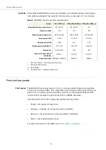
Front and rear panels
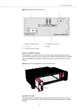
Figure 2
BOOSTIK front panel layout
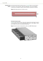
Koheras ACOUSTIK faceplate
The faceplate is mounted onto the front panel of the module casing and has four
screw holes that align with the mounting holes of the ACOUSTIK slots. Once inserted
into the ACOUSTIK, the module is fastened securely using four M4 x 0.7 mm pitch
screws.
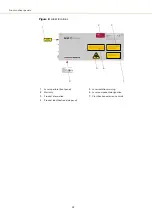
Figure 3
Inserting a BOOSTIK into an ACOUSTIK shelf
Input fiber connector
The optical input of a BOOSTIK is a threaded FC/APC connector. The connector is
designed to receive the seed optical signal from the optical output fiber of a BASIK
module.
1
Koheras ACOUSTIK faceplate
4
Output fiber and connector
2
5
Handle
3
FC/APC Input fiber connector
4
5
1
2
3
2
3
1
2
4x M4x0.7
Summary of Contents for Koheras BOOSTIK
Page 1: ...Item 800 631 01 Koheras BOOSTIK PRODUCT GUIDE Narrow linewidth laser amplifier...
Page 10: ...10...
Page 14: ...14...
Page 44: ...Module overview 44...
Page 51: ...51 Graphing Figure 37 Graphing tab X axis setting Y axes settings...
Page 52: ...Graphing 52...
Page 58: ...58 2...
Page 60: ...60 2...
Page 66: ...66...
Page 67: ......
Page 68: ...1 Koheras BOOSTIK Product Description Revision 1 0 09 2021 W 10456...


