


PD Dante
version 2.02 rev a - 31/10/18
16
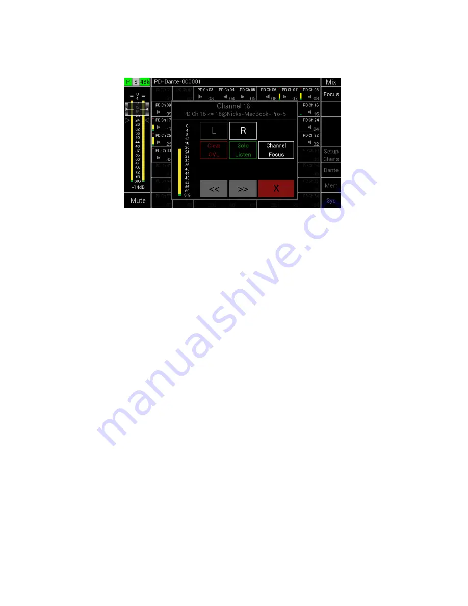
Channel Assignment Window
On pressing a Channel Cell the Channel Assignment window will open overlaying the Main
Input Screen
This window displays the following:
•
Channel Number
•
Dante RX Channel name and if there is a valid Dante connection the name and path
of that connection
•
A high-resolution meter showing the level of the currently selected channel
•
Left and Right assignment
o
Dark Grey indicates that the channel is unassigned
o
White indicates channels is assigned
o
Pressing a button toggles the function
•
Clear OVL – pressing this button clears the meter overload if it has set
o
Orange indicates that a peak signal has been detected on the selected
channel
o
Peak signal level to be detected is set up via the Sys Menu under the Meters
tab
o
Dark grey indicates no peak signal has been detected (default state)
•
Solo Listen – pressing this button will activate the Solo Listen function
o
On selection, this button will turn from dark grey to green
o
Main LR audio will be Muted
o
Selected channel audio will be routed to the LR output
o
Pressing the button, a second time or moving to another channel deactivates
this function and the main LR audio mix will be unmuted
•
Channel Focus – toggles channel focus for the currently selected channel
•
<< - pressing this button decrements one channel
•
>> - pressing this button increments one channel
•
X – pressing this button closes this window