background image


NWA100 Access Point


Chapter 2 Installation 

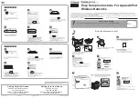
Installation procedures: 

1.


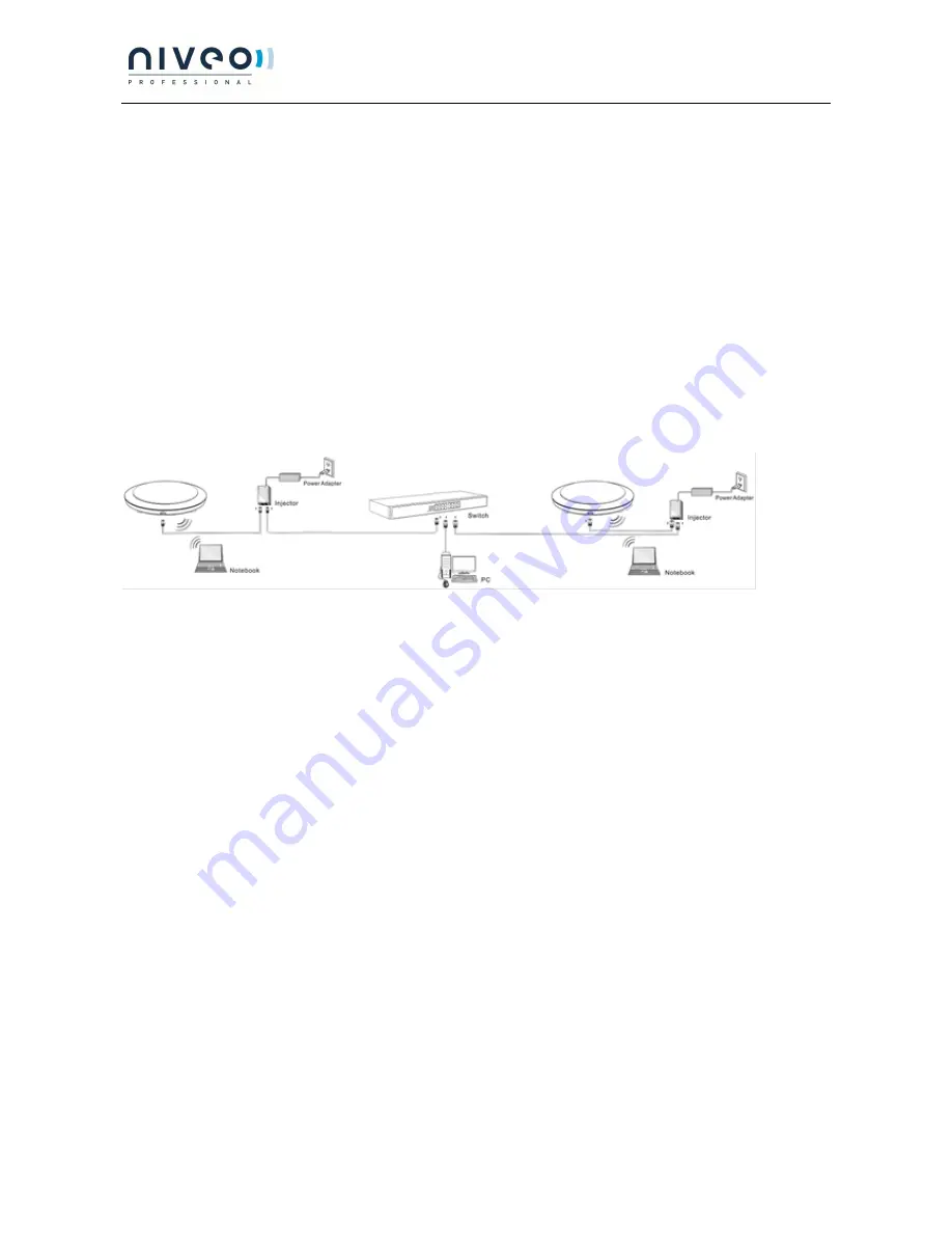
Connect the injector to the power adapter. 

2.


Connect the PoE port of the injector to the PoE port on this device with an Ethernet cable. 

3.


Connect the LAN port of the injector to the switch. 

4.


Hang the AP: 


  Install the bracket onto the ceiling or wall. 


  Fix the AP onto the bracket. 

The network topology is shown below: 


Summary of Contents for NWA 100

Page 1: ...NWA100 Access Point 1 Niveo Professional NWA 100 Wireless 900N Dual Band PoE Access Point Manual v1 3...

Page 2: ...do not constitute the warranty of any kind express or implied Warrantee complaints and return of goods Niveo warrants that the goods delivered by it are free of design material and manufacturing fault...

Page 3: ...F MERCHANTABILITY SATISFACTORY QUALITY OR FITNESS FOR A PARTICULAR PURPOSE ARE LIMITED TO THE DURATION OF THE WARRANTY PERIOD ALL OTHER EXPRESS OR IMPLIED CONDITIONS REPRESENTATIONS AND WARRANTIES INC...

Page 4: ...tics 10 3 3 4 Wireless Clients 10 3 4 NETWORK 11 3 4 1 LAN Settings 11 3 5 WIRELESS 12 3 5 1 Basic 12 3 5 2 Security 14 3 5 3 WDS 15 3 5 4 Universal Repeater 17 3 5 5 Access Control 18 3 5 6 Advanced...

Page 5: ...2 3ab IEEE802 3u IEEE802 3 auto sensing Gigabit port for data transmission or power supply Wireless rates of up to 450Mbps Unified Management allows network administrators to centrally manage APs on L...

Page 6: ...d Blinking Transferring data Back Panel RESET Restores the device to the factory default settings when pushed and held for 7 seconds This button has been hidden by the bracket of this device Before pr...

Page 7: ...to the power adapter 2 Connect the PoE port of the injector to the PoE port on this device with an Ethernet cable 3 Connect the LAN port of the injector to the switch 4 Hang the AP Install the bracke...

Page 8: ...and a Subnet Mask of 255 255 255 0 if you have changed the subnet of the wireless access point the computer you are using to connect must be within the same subnet If you are not clear about this con...

Page 9: ...ime 4 Number of Wireless Clients Displays the information of connected wireless clients if any 5 Firmware Version Displays Device s current firmware version 6 Hardware Version Displays Device s curren...

Page 10: ...ecurity mode 3 3 3 Traffic Statistics This section displays each SSID s traffic statistics 1 Total RX Traffic Total RX bytes SSID has received 2 Total RX Packets Total RX packets SSID has received 3 T...

Page 11: ...If no clients are connected to this device a prompt message will appear There is no wireless client connected to the device 3 4 Network 3 4 1 LAN Settings Here you can configure the LAN IP address sub...

Page 12: ...of 2 4GHz is 11b g n mixed 11b mode Select it if you have only 11b wireless devices in your wireless network Up to 11Mbps wireless rate is supported on this mode 11g mode Select it if you have only 11...

Page 13: ...t is enabled by default 4 AP Isolation Isolates clients connected to the same SSID 5 SSID This is the public name of your wireless network Select the SSID you wish to configure from the drop down list...

Page 14: ...ASCII characters 0 9 a z A Z _ can be included if you select ASCII or enter 10 or 26 valid Hex characters 0 9 a f A F can be included if you select Hex WPA PSK The WPA Wi Fi Protected Access protocol...

Page 15: ...e secured than WPA and WEP 1 Cipher Type Select AES advanced encryption standard or TKIP temporary key integrity protocol AES 2 Security Key Enter a security key which must be between 8 63 ASCII chara...

Page 16: ...Access Point 1 LAN IP 192 168 2 200 Access Point 2 LAN IP 192 168 2 223 WDS Mode Repeater Mode Configure Access Point 1 1 Enter the remote AP s MAC address and click OK 2 You can also scan the remote...

Page 17: ...the APs is in Bridge Mode the remote one must be in Repeater Mode 4 In Bridge mode clients won t be able to access the device s primary SSID 3 5 4 Universal Repeater Select Universal Repeater and enab...

Page 18: ...sted as Allowed will be able to connect to your wireless network all other wireless devices won t be allowed 2 To disallow a wireless device to connect to your wireless network select Deny enter its M...

Page 19: ...vice will send DTIM delivery traffic indication message and DTIM interval to wake clients up for receiving these packets Specify a valid value between 1 255 The default is 1 6 TX Power Percentage Cont...

Page 20: ...ngs after reboot Note When uploading software to the Wireless AP it is important not to disconnect the device from power supply If the power supply is interrupted the upload may fail corrupt the softw...

Page 21: ...nterval is 2 hours 3 Time Zone Select your local time zone 4 Copy Local Time Copy time on your PC to the device Note System time will be lost when the device is disconnected from power supply However...

Page 22: ...hard drive that can later be imported to your device in case that the device is restored to factory default settings To do so click the Backup button and specify a directory to save settings on your l...

Page 23: ...et mask 255 255 255 0 3 7 5 User Name Password Here you can change the user name and password for web login The default username and password is admin admin We suggest that you change this password to...

Page 24: ...NWA100 Access Point 24 3 7 7 LED This section allows you to modify LED status...

Page 25: ...ID is used to identify a particular 802 11 wireless LAN It is the name of a specific wireless network To let your wireless network adapter roam among different APs you must set all APs SSID to the sam...

Page 26: ...NWA100 Access Point 26 Appendix 2 Configure PC WIN7 OS Configuration 1 Click Start Control Panel 2 Enter Control Panel and click Network and Internet 3 Click Network and Sharing Center...

Page 27: ...NWA100 Access Point 27 4 Click Change adapter settings 5 Right click Local Area Connection and select Properties 6 Select Internet Protocol Version 4 TCP IPv4 and click Properties...

Page 28: ...NWA100 Access Point 28...

Page 29: ...ber between 1 253 in the IP address bar and 255 255 255 0 in the subnet mask and then click OK to save the configurations Windows XP OS Configuration 1 Right click My Network Places and select Propert...

Page 30: ...ss Point 30 4 Select Use the following IP address enter 192 168 2 X where x can be any number between 1 253 in the IP address bar and 255 255 255 0 in the subnet mask and then click OK to save the con...

Page 31: ...rt 15 of the FCC Rules These limits are designed to provide reasonable protection against harmful interference in a residential installation This equipment generates uses and can radiate radio frequen...

Page 32: ...environment This equipment should be installed and operated with minimum distance 20cm between the radiator your body NOTE 1 The manufacturer is not responsible for any radio or TV interference caused...

Reviews: