background image

TECHNICAL MANUAL

EN

Summary of Contents for T40

Page 1: ...TECHNICAL MANUAL EN ...

Page 2: ......

Page 3: ...the user to operate the system in the safest and most independent way and maintenance technicians carrying out programmed maintenance operations to ensure the correct operation of machinery and the system as a whole The manufacturer declines all liability for damage deriving from failure to observe the instructions given in this manual In case of doubts on the correct interpretation of instruction...

Page 4: ...cuum units for unintended purposes in industrial facilities in the presence of values of temperatures pressure and humidity in excess of those of normal workplaces Do not suck up liquids ashes in fireplaces large quantities of flour printer toner building site dust fine powder cement or plaster Unplug the unit from the 230V power supply wall socket in these cases I If the main vacuum unit receives...

Page 5: ...ation of main vacuum unit 2 4 Reversibility of suction and outlet connections 3 Self cleaning function 4 Maintenance 4 1 Emptying the dust container 4 2 Manual filter cleaning 5 Safety components 5 1 Protection fuse 5 2 Cut out breaker against overheating 6 Programming the user interface 6 1 General information 6 2 Personalization of maintenance parameters 6 3 Display of personalized maintenance p...

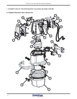
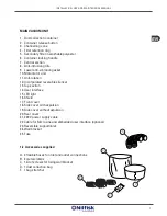
Page 6: ...INSTALLATION USE AND MAINTENANCE MANUAL 1 DESCRIPTION OF THE CENTRALIZED VACUUM CLEANING SYSTEM 1 1 Exploded diagram of main vacuum unit 12 1 2 3 4 5 6 7 8 9 11 14 15 16 13 17 18 19 20 24 21 22 23 10 25 ...

Page 7: ...Anti rotation 12 Incorporated reversible silencer 13 Top section 14 User interface 15 LED light 16 Shield 17 Front cover 18 Side cover with expulsion 19 Side cover without expulsion 20 Rear cover 21 230 V power supply cable 22 Cable for Micro Line and embedded user interface optional 23 Reversible support inlet 24 Wall bracket 25 Fuse 1 2 Accessories supplied A 2 flexible hoses for inlet and outle...

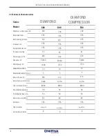
Page 8: ...aning function Air expulsion Incorporated silencer IP protection rating Power supply V AC Frequency Hz Motor power W ExternalSBfuse AM A SocketpowersupplyVdc SELV Max airflow m h Suction pressure mm H2 O Filter surface area cm Dustcontainercapacitylit Airinlet outletdiam mm Noise emission dB A Soft Start Filter material 1 3 Technical characteristics Current absorbed A 700 YES YES YES YES 44 230 50...

Page 9: ... EN INSTALLATION USE AND MAINTENANCE MANUAL DIAMOND COMPRESSOR DIAMOND ...

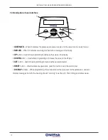
Page 10: ...hile programming to decrease the value on the display 4 DOWN button Used while programming to increase the value on the display 5 SET button Used while programming to memorize the new parameters 6 RESET button After maintenance operations press this button to zero the alarm timer 7 DISPLAY window While programming this window shows the values set for the parameters and also displays messages to cl...

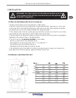
Page 11: ...ding like garage and technical service room External places are allowed provided that the vacuum unit is always protected from inclement weather The selected position must have a clear space around the main vacuum unit and well lit so as to make easy maintenance and repair Install a 230 V SHUKO power supply socket The wall mounts must allow the installation of the main vacuum unit off the ground a...

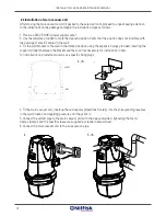
Page 12: ...ll bracket to the wall in the marked position using the expansion plugs provided inserting the support cylinders between the bracket and the wall not necessary for installation in box For installation on plasterboard walls use specific fixing plugs 4 Fit the main vacuum unit inserting the rectangular projections frontally into the corresponding recesses in the wall bracket and applying pressure un...

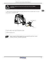
Page 13: ...low voltage command of the INLETS LINE 8 Insert the power supply plug into the electrical socket 9 Perform the system trial CAUTION Electrical connections must be made only by qualified personnel At the completion of the installation it is recommended to perform a control of the main vacuum unit fixation and stability Power supply 230 V 12 V ...

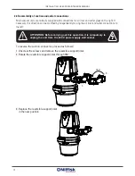
Page 14: ...e modified by independently moving the air inlet and outlet connections to the left To reverse the suction connector proceed as follows 1 Unscrew the screws and remove the reversible support inlet 2 Rotate the reversible support inlet through 180 3 Replace the reversible support inlet in the new position 1 2 ATTENTION Before carrying out this operation it is compulsory to unplug the unit from the ...

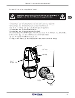
Page 15: ...5 Unscrew the screws and remove the reversible silencer 6 Rotate the silencer through 180 replace it inside the top section Ensure that the O rings of the central section are correctly positioned and that there are no disconnected cables 7 Replace the top section on the main vacuum unit 8 Replace the rear cover front cover shield and side covers with and without expulsion ATTENTION Before carrying...

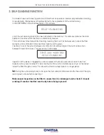
Page 16: ...ter cleaning will be given The time of use of the system between one indication of self cleaning and the next can be varied between 30 and 240 minutes The preset time is 90 minutes Operation of the device is triggered by a mini compressor that feed a pressure air tank of one liter capacity until a pressure value of 5 bar is reached At this point an instantaneous air jet is channelled inside the fi...

Page 17: ... least once a year Dry it thoroughly before replacing it INSTRUCTIONS 1 Unplug the unit from the 230 V power supply wall socket 2 Open the dust container by releasing the left hand and right hand hooks Then press the central button A to release the handle and obtain opening of the container downwards B 3 Remove the dust container C from the main vacuum unit body pulling it towards yourself 4 Remov...

Page 18: ...ilter must be replaced after three years of standard use 1 Unplug the unit from the 230 V power supply wall socket 2 Release and remove the dust container 3 Unscrew and remove the filter retention ring fig 1 4 Carefully remove the filter 5 Replace with the spare filter resting it against the ring and screw it fully in 6 Replace the dust container taking care to fit it correctly 7 Connect the unit ...

Page 19: ...ics 5 2 Cut out breaker against overheating All main vacuum units are fitted with a thermal cut out breaker that stops the motor in case of overheating In case of unit stop due to thermal cut out breaker allow the motor to cool down to normal operating temperature about 25 30 minutes Then trace the cause of overheating e g clogged filter full dust container partial obstruction of a brush or flexib...

Page 20: ...s With the procedures described here users can modify the preset maintenance parameters or the personalized values programmed previously with a series of simple operations on the user interface Filter cleaning This procedure is used to modify the parameter that controls alarm operation For the preset values consult the above chart Enter the USER MENU by pressing the SET button when the display sho...

Page 21: ...morize the new value entered keep the SET button pressed down for a few seconds until the MEMORIZED message appears To leave this display press the RESET button Continuous operation This procedure is used to modify the parameter that controls alarm operation set by default at 45 minutes Enter the USER MENU by pressing the SET button when the display shows the STANDBY message Scroll through the USE...

Page 22: ... 7 2 Suction power is very low Check that The other suction points are closed There are no foreign bodies trapped in the brush flexible hose or curved joint The dust container is correctly installed and is not full The filter cartridge is correctly positioned and is clean The main vacuum unit is correctly connected to the suction pipe The suction pipe is blocked or has no leaks IF THE MAIN VACUUM ...

Page 23: ... refuse but must be taken to a suitable collection centre for the recycling of electrical and electronic devices By disposing of this product in a suitable way you will contribute in avoiding potential damage to the environment and public health that could be caused by unsuitable product disposal For more detailed information on recycling procedures for this product contact your local authority yo...

Page 24: ...irectives Machinery Directive 2006 42 EC MD Low Voltage Directive 2006 95 EC BT EN 60335 1 EN 60335 2 2 EN 50366 Electromagnetic Compatibility Directive 2004 108 EC EMC EN 55014 EN 61000 Pressure Equipment Device 97 23 CE PED only for T40 model The instruction manual indicates in particular the standards for the installation use and maintenance of this device The responsible to form the relevant t...

Page 25: ...Company with UNI EN ISO 9001 2000 Certified Quality System Nilfisk Advance A S Sognevej 25 2605 Brøendby 7218210 Denmark www nilfisk com ...

Reviews: