SR 9772
5/09 FORM NO. 56041803
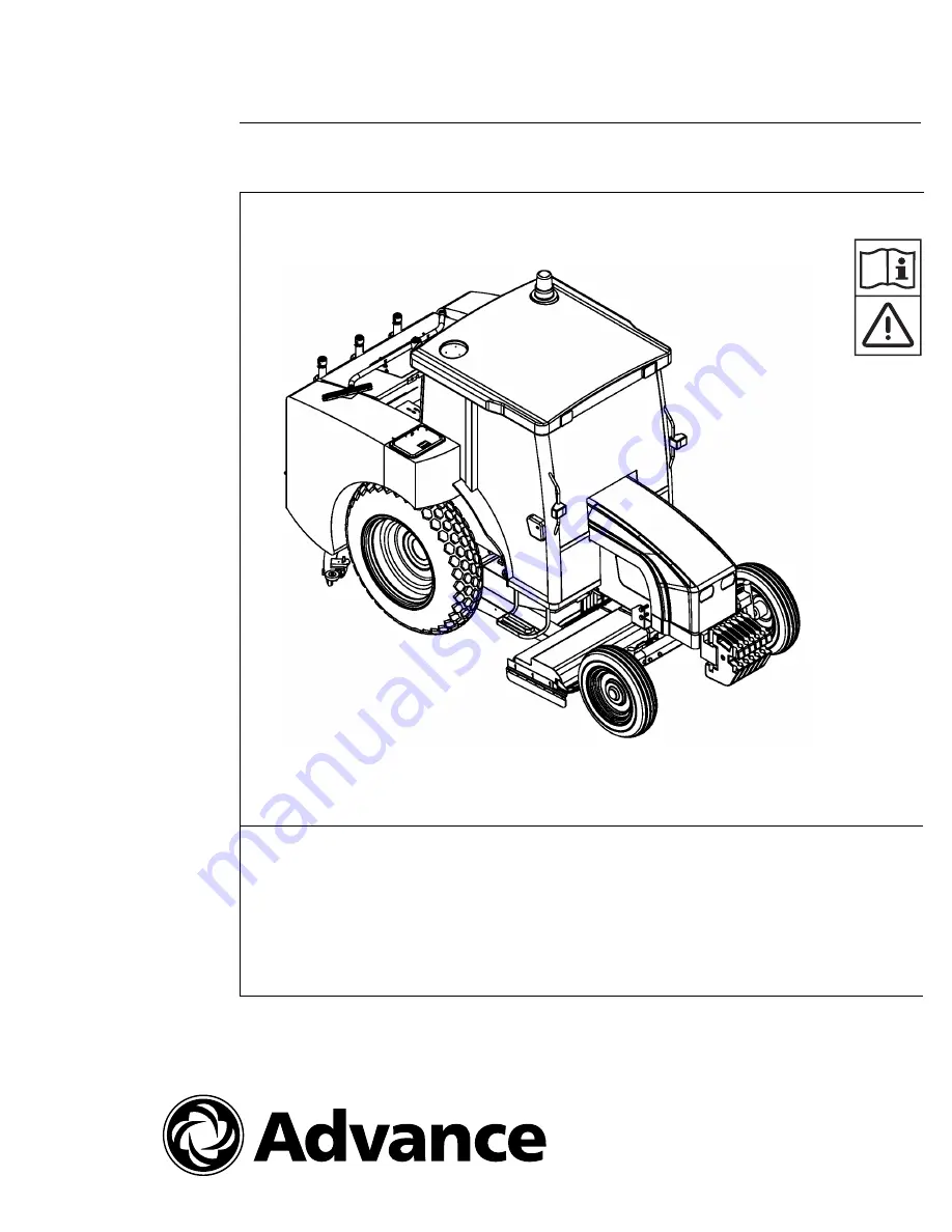
INSTRUCTIONS FOR USE
MODELS 56109414, 56109415, 56109416, 56109417
English
https://harrissupplyind.com - To Order Parts Call 608-268-8080
Page 1: ...SR 9772 5 09 FORM NO 56041803 INSTRUCTIONS FOR USE MODELS 56109414 56109415 56109416 56109417 English h t t p s h a r r i s s u p p l y i n d c o m T o O r d e r P a r t s C a l l 6 0 8 2 6 8 8 0 8 0 ...
Page 2: ...crubbing Systems 14 15 Operating the Scrubber Controls 16 17 Operating Instructions 18 26 Service Chart 27 Service Instructions 28 33 Troubleshooting Scrubbing System 34 Troubleshooting Hydraulic System 35 Troubleshooting Camel Recycling Pump 36 Troubleshooting Camel Detergent Pump 37 TABLE OF CONTENTS h t t p s h a r r i s s u p p l y i n d c o m T o O r d e r P a r t s C a l l 6 0 8 2 6 8 8 0 8 ...
Page 3: ...he wall of the operator s compartment This information is needed when ordering repair parts for the machine Use the space below to note the Model Number and Serial Number of your machine for future reference MODEL _______________________________________________ SERIAL NUMBER _______________________________________ Note Reference the separately supplied engine manufacture s maintenance and operator...
Page 4: ... automatic advance Type Bosch VE3 Fuel Filtration Mesh filter in the fuel pump replacement cartridge filter on the injection pump feed line with water separator Lubrication Pressurized by gear pump Oil filtration pressurized through pump intake mesh and replacement cartridge filter on engine intake ENGINE LUBE PRESSURE Engine Speed 2000rpm bar 2 9 3 9 psi 42 24 55 47 Cooling Water pressurized circ...
Page 5: ... construction crossover lines hoses allows filling from either side clean out doors and oversize fill openings are standard RECOVERY TANK One 1 210 gallon capacity stainless steel construction equipped with automatic vacuum shut off float VACUUM SYSTEM Power provided by a regenerative air turbine V belt driven SCRUB BRUSHES Four 4 18 inch diameter disc type Brushes are mounted to a 3 8 steel frame...
Page 6: ...6 FORM NO 56041803 SR9772 MACHINE DIMENSIONS h t t p s h a r r i s s u p p l y i n d c o m T o O r d e r P a r t s C a l l 6 0 8 2 6 8 8 0 8 0 ...
Page 7: ...SR9772 FORM NO 56041803 7 MACHINE DIMENSIONS h t t p s h a r r i s s u p p l y i n d c o m T o O r d e r P a r t s C a l l 6 0 8 2 6 8 8 0 8 0 ...
Page 8: ...e practices which could result in equipment damage WARNING Machines can ignite flammable materials and vapors Do not use with or near flammables such as gasoline grain dust solvents and thinners WARNING Improper use of heavy machinery can cause personal injury WARNING Operate only when lids doors and access panels are securely closed WARNING Use care when reversing machine in confined area WARNING...
Page 9: ...esignated controls Always operate in well lighted areas WARNING Do not carry passengers on the machine Set the Parking Brake when leaving the machine Chock block the wheels if the machine is parked on a grade ramp or is being prepared for Maintenance WARNING Never leave the operator s compartment with engine running WARNING Report damage or faulty operation immediately Do not operate the machine u...
Page 10: ...Only tow for short distances 2 Do not exceed 5 mph 8 km h 3 If possible run the engine to lubricate the power steering components 4 Position the gear and range levers in neutral CAUTION Never use ropes or cables to tow the scrubber These may slip or break presenting the risk of serious injury CAUTION Never exceed 5 mph 8 km h when towing Effort to control steering is much greater and response much...
Page 11: ...on level always add part water to part anti freeze 4 In addition to regular service operations listed the following items should be checked every 10 hours or daily during the first 50 hours of operation Engine Oil Level Rear Axle Oil Level at turbine cover access Rear Wheel Nuts for Tightness NEW HOLLAND TN60 TRACTOR POWER UNIT The Advance SR9772 utilizes a NEW HOLLAND TN60 as the power unit The p...
Page 12: ...er 6 When driving on roads indicate all intentions to stop turn or slow down use appropriate warning devices to indicate a slow moving vehicle CAUTION When SHIFTING from one range to another forward to reverse or reverse to forward the operator MUST reduce the speed throttle to LOW IDLE shift range and or gear then increase the speed throttle STARTING THE ENGINE 1 If the scrubber has not been used...
Page 13: ... in the diesel fuel which leads to a reduction in fluidity and subsequent fuel supply problems mix the diesel fuel with antifreeze or similar product in the proportions described on the container Put the antifreeze in the tank first followed by the fuel The antifreeze will ensure there is optimum fuel supply to the engine without reducing performance up to 20º C 68º F The diesel must be mixed with...
Page 14: ...ork to dislodge dirt and grime As the machine moves forward the solution vacuum system lifts dirty water and debris from floor surface through the squeegee tools and a recovery tank air water separation system A float switch in the tank activates an indicator light on the control panel when the water level in the tank becomes too high Debris and sludge settle to the bottom of the recovery tank h t...
Page 15: ...ere a system of baffles helps to clarify the solution on its way to the pumping chamber of the recovery tank At intervals a system of sensors activates the recycling pump which sends filtered solution from the pumping chamber on its way to the centrifugal separator which further aids clarifying of the solution for re use In the separator solids are removed and purged into the containment chamber T...
Page 16: ...he upper portion will result in the brushes rotating clockwise pressing the lower portion will cause the brushes to rotate counterclockwise 4 Squeegee Vac Fan Switch Pressing momentarily the contact switch switch will lower the squeegee and turn on the vacuum fan pressing the upper portion will raise the squeegee and shut off the vacuum fan IF THE MACHINE IS PLACED IN REVERSE the squeegee automati...
Page 17: ...n the squeegee will automatically lower and the solution vacuum will be turned on Cab Model Platform Model Prior to engaging any of the switches on the control panel the tractor s hydraulic lever must be engaged by pulling it back During transport make sure the scrub deck and squeegee are in the raised position and the tractor hydraulic lever is in the FORWARD OFF position HYDRAULIC LEVER HYDRAULI...
Page 18: ...and hold the switch in upward position for 2 seconds and release The switch will return automatically to a neutral position Confirm the scrub deck and squeegees are in the raised position 7 Push the hydraulic control lever forward to off de energize 8 Move the scrubber to filling station by first reducing the throttle to low idle following start up depress clutch select range and gear slowly relea...
Page 19: ...ing instructions release the parking brake and drive the scrubber to work area by first reducing the throttle to low idle following start up depress clutch select range and gear slowly release clutch and increase throttle 16 Stop the machine by depressing the clutch and reducing throttle to low idle move range and gear levers to neutral apply brakes 17 Depress clutch and select the appropriate gea...
Page 20: ...ue moving over the scrub area until the squeegee recovers the solution 28 Activate the switch at the control panel to raise the squeegee and turn off the vacuum system Press and hold the switch in an upward position for 2 seconds and release the switch will return automatically to a neutral position Confirm that the squeegee is raised and the vacuum has stopped 29 Move the hydraulic control lever ...
Page 21: ...ving any excess chemicals or detergent Rinse doors and seals close the door and pivot t bolt and tighten knobs EXTENDED SCRUBBING CAMEL MODE Operating Instructions 1 Access the scrubber 2 Check all scrub systems verifying that they are in the off position 3 Confirm the hydraulic control lever is in off position all the way forward 4 Follow the same New Holland procedure for starting tractor 5 Pull...
Page 22: ...nks are full 15 While solution tanks are filling inspect the machine Check and clean out doors ensure the doors are sealed properly and inspect the squeegee blades Perform maintenance as required 16 Close the solution tank access doors once the tanks are filled 17 Start the scrubber following New Holland operating instructions release the parking brake and drive the scrubber to work area by first ...
Page 23: ...ery tank float ball will also activate when the tank is full The vacuum airflow bypass will activate discontinuing solution recovery 34 Activate the switch at the control panel to raise scrub deck Press and hold the switch in upward position for 2 seconds and release the switch will return automatically to the neutral position Confirm that the scrub deck is in the raised position 35 Continue movin...
Page 24: ... speed throttle to LOW IDLE shift range and or gear then increase the speed throttle 9 Stop the machine by following the throttle and range and shifting procedures 10 Select the appropriate gears to scrub at a speed of 2 3 mph 11 Activate the squeegee switch on the scrubber control panel squeegee down vacuum on 12 Pull the hydraulic control lever back to energize 13 Begin the solution recovery 14 ...
Page 25: ... the plug on upper left corner of recovery tank and flush the system with the hose This removes debris in the squeegee recovery system 29 Replace the plug once it is clean OPERATION ON GRADES The machine may be operated on grades up to 8º if the surface provides adequate traction WARNING Always test wet surface traction part way up or part way down sloped area so that if slipping does occur contro...
Page 26: ...ts Remove the clean out cap located on top of the recovery tank Inspect and flush the pick up tubes and squeegee hose HELPFUL HINTS FOR CLEANING OPERATION WARNING Do not turn the steering wheel sharply when the machine is in motion The scrubber is very responsive to movement of the steering wheel Do not make sudden turns Follow these hints to get the best possible cleaning results Scrub in straigh...
Page 27: ...tor maintenance see tractor manual EVERY 100 HOURS 16 Lubricate squeegee casters 17 Lubricate all moving joints brush and squeegee lift 18 Lubricate head lift chain and sprockets 19 Clean solution tank and filter screen Perform recomended New Holland tractor maintenance see tractor manual EVERY 300 HOURS 20 Change engine oil and filter 21 Change hydraulic system filter 22 Clean engine air filter 2...
Page 28: ...UEEGEE The squeegee will require service when the inner edges of the blades become round with wear impairing the wiping action or water pickup To service the rear squeegee use the following steps 1 Loosen the aluminum knobs these hold the squeegee tool to the squeegee support 2 Remove the squeegee tool and turn upside down to service the blades or caster wheels The squeegee blades are designed to ...
Page 29: ...3 16 above the flat surface Lock jam nuts SQUEEGEE VACCUM HOSE Check squegee vaccum hose for wear cracks or damage FUEL NOZZLE Before starting the scrubber make sure that there is enough fuel in the tank The fuel nozzle is located on the front of the scrubber to the left side under the fender Fuel up regularly to prevent the engine stalling and interruption of cleaning cycle Add the appropriate fu...
Page 30: ... with the same size fuse to prevent damage to the electrical circuit SOLUTION FEED HOSES To check solution hoses for damage remove cover by unscrewing the nut on the side of the cover Clean and check hoses for cracks or leaks Replace damaged hoses to prevent loss of solution h t t p s h a r r i s s u p p l y i n d c o m T o O r d e r P a r t s C a l l 6 0 8 2 6 8 8 0 8 0 ...
Page 31: ...lt tension should be checked periodically thereafter To adjust belt tension Open turbine cover loosen bolts tighten adjusting nut to increase tension proper setting is 1 2 deflection of the belt with 25 lbs of pressure at midpoint between the two pulleys then re tighten bolts SPLASH SKIRT ADJUSTMENT Adjust the right and left side skirts with brush wear to maintain minimal floor clearance h t t p s...
Page 32: ...rain plug To clean To remove sludge after draining open all the drain doors hose out tank interior to flush sludge The float and float cage should be flushed clean Remove clean out cap and flush pick up tube and squeegee hoses NOTE Sludge accumulations greater than 2 will tend to clog the drain plug and drain hose SERVICING THE SOLUTION TANK Standard Machine Periodically remove and clean out the s...
Page 33: ...f valve is located on top of the recovery tank and is part of the air inlet system for the solution vacuum To check the factory setting 1 Remove the squeegee suction hoses from the recovery tank pick up hoses 2 Cover inlet pipe must be air tight seal 3 Run engine at 2000 rpm 4 Place vacuum gauge on other inlet pipe and check reading To adjust relief valve setting 1 Hold the stem to keep it from tu...
Page 34: ... inlet 3 Vacuum turbine not operating 4 Vacuum float shut off 5 Drain plug missing or drain door leakage or not properly closed 1 Disconnect suction hose from squeegee flush squeegee hoses 2 Check all hose connections for looseness or damage 3 Check all air discharge at turbine muffler Check for slipping or broken drive belt 4 Excessive solution recovery drain tank Excessive foam build up change c...
Page 35: ...ition 3 Worn gear pump 4 Hydraulic system not engaged 1 2 Actuate system 3 Repair or replace Repair or replace 4 Engage hydraulics TROUBLESHOOTING HYDRAULIC SYSTEM Brushes not lowering 1 No power to control panel 1 Check electrical connection and fuse PROBLEM PROBABLE CAUSE REMEDY Failure to lift with shift lever in reverse control lever up 1 No power to control panel 2 Switch contact 1 Check elec...
Page 36: ...ximum pressure is 40 psi Check for obstructions at discharge port 2 Replace parts check alignment and pressure at discharge ports 40 psi 3 Replace part check pressure at discharge port 4 Check mounting to be sure pump is securely mounted to base Pump will not prime 1 Air leak in suction side 1 Check all pipe connections at suction side Noise during operation 1 Starved suction 2 Bearings worn 3 Bro...
Page 37: ...ng or motor 3 Fluid level low or empty Motor operates but pump output is low or stopped PROBLEM PROBABLE CAUSE REMEDY 1 Check connection and tighten 2 Replace motor 3 Turn Camel switch to on position 1 Clean out detergent lines 2 Replace wiring or motor 3 Check fluid level TROUBLESHOOTING CAMEL DETERGENT PUMP h t t p s h a r r i s s u p p l y i n d c o m T o O r d e r P a r t s C a l l 6 0 8 2 6 8...
Page 38: ...h t t p s h a r r i s s u p p l y i n d c o m T o O r d e r P a r t s C a l l 6 0 8 2 6 8 8 0 8 0 ...
Page 39: ...h t t p s h a r r i s s u p p l y i n d c o m T o O r d e r P a r t s C a l l 6 0 8 2 6 8 8 0 8 0 ...
Page 40: ...h t t p s h a r r i s s u p p l y i n d c o m T o O r d e r P a r t s C a l l 6 0 8 2 6 8 8 0 8 0 ...