SD 400 / SD 430 / SD 500 / SDP 430
2 _2 Technical data / 2 _3 Structure and accessories
14
2 _2
Technical data
Table 1
Subject to change without notice.
2 _3
Structure and accessories
2 _3.1
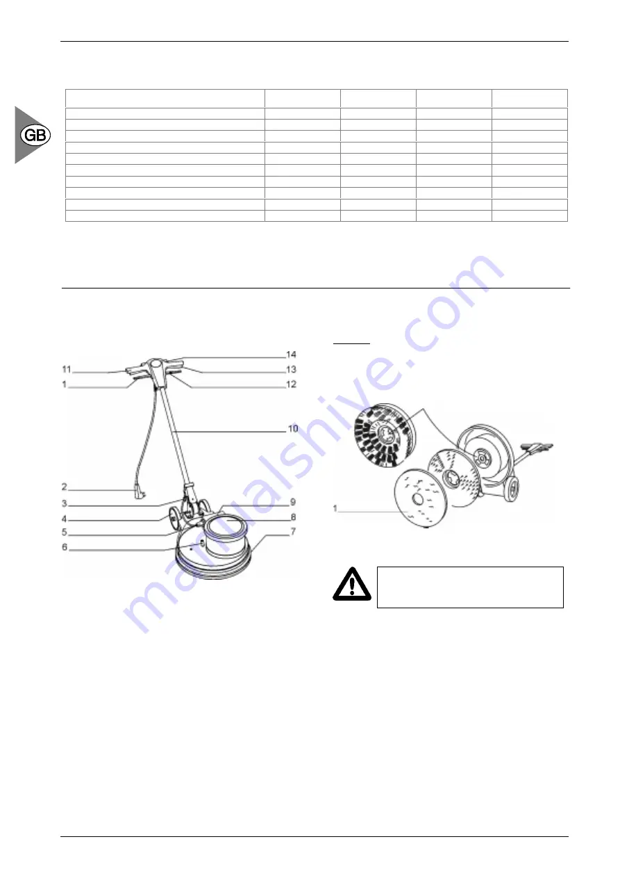
General view
Picture 1
1
Handle height adjustment lever
2 Mains
cable
3
Mains connection lead
4 Transport
wheels
5 Appliance
socket
6
Water supply hose
7 Bumper
8 Motorcover
9
Capacitor housing with appliance plug
10 Handle height adjustment lever
11 Handle
top
12 Control lever for tank / spray unit
13 On / off lever
14 Safety catch levers
2 _3.2
Installation of the brush / pad holder /
pad replacement
Picture 1: Press handle height adjustment lever (1). Put
handle (10) into upright position. Tip machine
backwards over the transport wheels (4). Line up the
catch plate of the brush or drive disc with the driver.
Turn brush or drive disc clockwise to lock.
Picture 2
Attention! When using a drive disc make
sure the machine is not started without a
floor pad under the disc.
When using a rubber-plate drive disc for thin pads a
floor pad on the ground and guide the machine into
position over the pad.
When using a drive disc with padholder-plate press a
pad onto the drive disc: fit the drive disc to the machine
and lift the machine into working position.
Designation
SD 400
SD 430
SD 500
SDP 430
Operating width
mm
430
430
510
430
Operating height
mm
Clearance height
mm
Operating voltage
V/Hz
230/50
230/50
230/50
230/50
Rated output
W
750
1100
1100
1200
Speed
rpm
155
155
155
380
Brush application pressure
N/cm
2
0,42
0,56
0,45
0,43
Mains connection lead - length
m
12
12
12
12
Operating weight
kg
39
52
59
40
Noise level
dB(A)
56
56
56
58
Summary of Contents for SD 400
Page 91: ...SD 400 SD 430 SD 500 SDP 430 ...