34
- FORM NO. 56043071 CMAX
™
28/34ST / I-MAX
™
28/32C, BA 750/850ST, BA 750C
RECOVERY SYSTEM
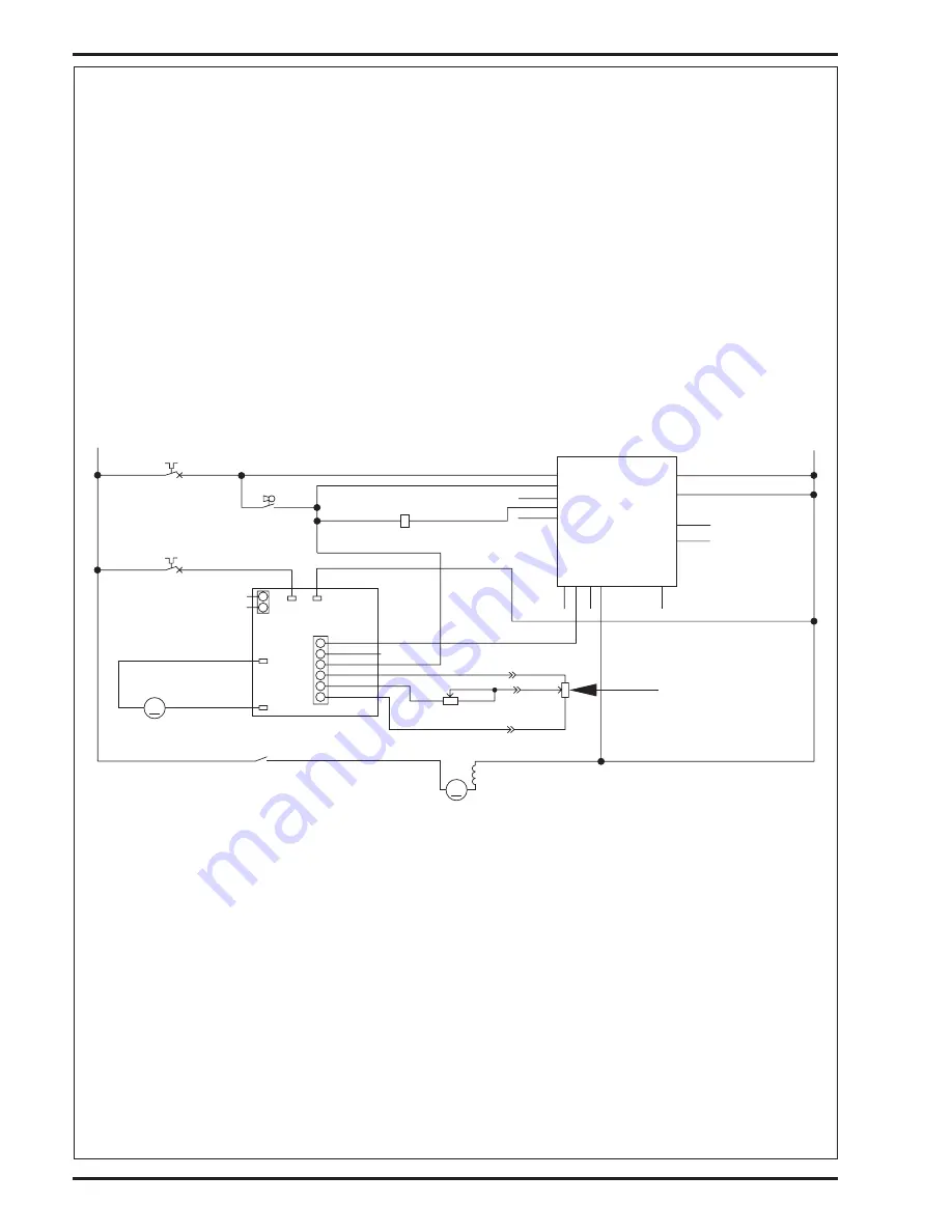
VACUUM MOTOR CONTROL CIRCUIT OVERVIEW (AUTO MODE)
See Figure 2.
+(Positive) Circuit input starts with:
•
A closed S3 key switch supplies the needed positive voltage to the K2 vacuum motor solenoid coil and the A1 control board #1terminal (Brn
wires). Note: The A1 control board scrub-on/pressure increase button must also be depressed (enabled). This operator command lowers
the brush deck.
-(Negative) circuit input starts with:
•
A battery negative ground input at the A1 control board terminal #4 and at the A2 speed controller terminal B- (T2).
•
A negative voltage output from the A2 speed controller’s P1 (pin #1) to the A1 control boards yellow wire (#3 terminal). Note: The A2 speed
control auxiliary output (pin #1) occurs whenever the R1 directional/throttle pot is moved off its neutral setting. This operator command
happens when the drive paddle is pushed or pulled to run the wheel drive motor in Fwd or Rev.
•
A negative voltage output from the A1 board’s terminal #6 Blk/Yel wire completes the K2 solenoid coil circuit (Pos. & Neg.) and pulls in the
solenoid load contact making the vacuum motor run.
FIGURE 2
Electrical Diagram
*For complete description of all callouts see Electrical System
Wiring Diagram
.
BLK
A1
CONTROL BOARD
BLK/WHT
4
13
B-2
B-3
14 B+2
1 B+1
5
6 VACUUM CONTACTOR
7
11
12
FOR/REV
VAC MOTOR
2
9
8
3
10
ORN
RED
GRN
F2
Circuit Breaker
5 AMP
S3
Switch
SPST Key
GRN
BRN
BRN
K2
BLK/YEL
Coil, Vac Motor Contactor
RED
F3
WHT/YEL
BRN
YEL
BLK
1
2
M4
M
Vacuum Motor
BLU
RED
K2
R1
POT. 5K OHM THROTTLE
A2
1208 SPEED CONTROLLER
M1
M
+
-
B-
(T2)
B+
(T1)
B+
B-
P2
(T3)
M1
(T4)
M2
P1
1
2
1
2
3
4
5
6
OUTPUT
OUTPUT
KEYSWITCH
REVERSE
WIPER
FORWARD
+
-
VIO
BRN/WHT
GRN/YEL
1
3
2
POT. 25K OHM SPEED LIMIT
1
2
2
3
1
RED/BLK
GRA
R2
+
BLK
revised 12/04


