background image

28

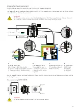
Water after-heating element - duct installation

The water heating element is for duct connection and it cannot be integrated into the ventilation unit.

Connect up the system, air it, and check for potential leaks. You can now start the unit. 
Following adequate flushing of the system, check and clean the sediment trap.

IMPORTANT regarding Danfoss actuator type AME 140:

Reinstallation of the actuator must be done as follows: 
1. Disconnect the power supply and remove the cover from the actuator
2. Release the gear by pressing and holding the button at the bottom of the casing, while turning the spindle fully (anticlockwise)
3. Install the actuator and connect up the power supply
4. Move DIP-switch no. 1 to ON, and then to OFF
5. It calibrates automatically for up to 6 minutes. (The diode flashes during calibration. After completion, it stays on)
6. Put the cover on the actuator

Dimensional drawing Ø125/Ø160/Ø200

:

WARNING

The water after-heating element must be installed by a certified plumber.

WARNING

If you install the water after-heating element outside the climate screen of the building, it must be protected against 
frost.

Supply flow

Return flow

The water heating element is supplied as an ac

-

cessory consisting of: 
1. Water heating element with T9 temperature 

sensor and frost thermostat B3

2. Actuator and regulation valve

Danfoss AME 140/24V 0-10V signal, 2-way 
valve VZ2 Kv 0.4 (Nilan supply) the Kvs value 
must be checked against the power supply.
Differential pressure: 0.1 - 0.6 bar.
With a flow temperature of 60°C and at max

-

imum heat output, the temperature is esti

-

mated to fall with 20°C over the heating 
element.

3. Bleed valve (not supplied by Nilan)
4. Sediment trap (not supplied by Nilan)

ATTENTION

The after-heating element must be activated in the Software under Basic settings.

1

3

2

4

 83 

 310 

 440 

 Ø 

 238 

 22 

 32 

 31 

 300 

1/2" RG

1/2" RG

Summary of Contents for Comfort 350 Top

Page 1: ...INSTALLATION INSTRUCTIONS Comfort 350 Top Comfort 350 Top Polar CTS602 LIGHT BY NILAN Version 5 00 27 10 2021 M24 Comfort 350 Top GB...

Page 2: ...nctional cable 11 Gateway with App option 11 Set up Mounting 12 Positioning of the ventilation unit 12 Top unit 12 Mounting the ventilation unit 12 Duct connections 13 Electrical installation Electric...

Page 3: ...multaneous with fire automation system 31 Alarm code 32 Start up and annual testing 32 Schedule for functional testing 33 Ventilation installation Duct system 34 Legislation 34 Ducts 34 Ventilation un...

Page 4: ...your nearest Nilan dealer A list of Nilan dealers is available on www nilan dk From factory the unit has been tested and is ready for operation CAUTION Always disconnect the power supply to the unit i...

Page 5: ...in for instance bathroom lavatory kitchen andutilityroom Itthen blowsfresh outdoorair in throughvalvesplacedinliving areassuchassitting room family room andbedrooms The cold outdoor air is heated up b...

Page 6: ...m Right version Left version Connections 1 Outdoor air 2 Supply air 3 Extract air 4 Discharge air 5 Condensate drain NB Spouts for inlet ring 1 3 4 2 5 550 1 6 0 119 180 119 180 109 109 148 148 105 55...

Page 7: ...Right version Left version Connections 1 Outdoor air 2 Supply air 3 Extract air 4 Discharge air 5 Condensate drain NB Spouts for inlet ring 1 6 0 119 180 119 180 109 109 148 148 790 906 1 2 3 4 5 550...

Page 8: ...ain 6 Electrical or water after heating element connec tions Automation T2 T7 Supply air temperature sensor T3 Extract air temperature sensor T4 Discharge air and de icing temperature sensor T1 T8 Out...

Page 9: ...to place it within the climate screen It comes with the necessary sensors and connectors Installing an after heating element will allow you to control the supply air temperature in the following case...

Page 10: ...on of user selection 1 cooker hood Connection of Modbus communication to for instance CTS unit You connect the box up with the supplied 1 m cable with RJ45 connector If you want to run the cooker hood...

Page 11: ...stalled The control panel for the ventilation unit is connected up with a short wire so it can be installed close to the unit If you place the unit so the control panel is out of sight for instance in...

Page 12: ...N When positioning the unit you should always consider future service and maintenance It must be easy to replace filters and it must be possible to remove for instance the exchanger and to replace fan...

Page 13: ...13 Duct connections An inlet ring needs to be fitted not supplied by Nilan 1 Use size 160mm inlet ring 2 Press the inlet rings firmly into the ventilation nozzles...

Page 14: ...nnection to control panel 2 Connection 230V remember electrical grounding 3 External connections accessories via RJ45 plug 4 Connection to PC CAUTION The power supply is plugged into a 230V socket wit...

Page 15: ...the unit ATTENTION If you want a longer cable use a standard LAN cable max 50 meters Nilan offers a 15 meter cable with plugs on both ends The wall bracket is located at the back of the panel You can...

Page 16: ...tat external fire automation system Modbus B1 Modbus A1 User selection 2 User selection 1 GND GND ATTENTION If you only want toconnect 1 function we will recommend that you purchase a LAN cable type A...

Page 17: ...o the ventilation unit when you switch it on When this happens the ventilation unit increases the air volume to the set level so that enough air is drawn through the cooker hood Fireplace wood burning...

Page 18: ...odbus communication Establish the Modbus connection via the following 1 Green white 4 Blue 5 Blue white NB If fire thermostat external fire automation system is not connected up make a shunt between 1...

Page 19: ...you connect up an external fire automation system it will be necessary for the ventilation unit torestart automatically You can set for this to happen on the control panel Please consult the software...

Page 20: ...here may be times when the air volume is insufficient for cooker hood extraction Ifyouinstall anEM box youcanregulate the extractedairwhenthe cookerhood is in operation so that less air is drawn from...

Page 21: ...space in the in stallation for an EM box an alternative solution may be to install a DTBU damper in the duct sys tem It works the same way except from the fact that it has no integral particle filter...

Page 22: ...nt has a three step safety system that prevents overheating 1 An operating thermostat regulates the heating and ensuresthat the supply air temperature does not fall below 1 C 2 Should the temperature...

Page 23: ...Mount the large circuit board supports in the 3 holes on the expansion PCB 3 Connect the expansion PCB to CN9 Mount the circuit board supports in the holes provided for this on the CTS602 Light circu...

Page 24: ...the heating element The T2 sensor must be disconnected from the circuit board and the T7 sensor must then be connected to where the T2 sensor was previously connected A Connection on the CTS602 Expans...

Page 25: ...t disconnected from the circuit board and the T7 sensor must then be connected to where T2 sensor was previously connected A CTS602 Expansion PCB 0 10V Orange GND Orange white B3 Frost protect Green G...

Page 26: ...ntrol panel is locat ed in the same place An external alarm indicator in the form of an electric bulb or an acoustic signal can be connected to the ventilation unit and announce when an alarm occurs T...

Page 27: ...gainst frost Illustration of connection at the bottom of the unit ATTENTION There is positive pressure in the condensate drain in the ventilation unit and it is therefore not necessary to install a wa...

Page 28: ...completion it stays on 6 Put the cover on the actuator Dimensional drawing 125 160 200 WARNING The water after heating element must be installed by a certified plumber WARNING If you install the wate...

Page 29: ...ed fire and smoke dampers will close and the ventilation unit will stop If the ventilation unit stops fire and smoke dampers will close Dampers that are connected up to the system must have a 24V or 2...

Page 30: ...screw terminal S1 GND Connect S2 white to screw terminal S2 Damper closed signal Connect S3 white to screw terminal S3 Connect S4 white to screw terminal S4 GND Connect S5 white to screw terminal S5 C...

Page 31: ...re automation system If the Fire automation system has been activated in the software and you want to run cooker hood extraction in combination with an EM box DTBU damper Nilan can supply a Connection...

Page 32: ...asin case of fire The test must be performed again until OK is displayed in the menu For the overall system all requirements in DS 428 must be met before a delivery can be made Manual test of fire an...

Page 33: ...33 Schedule for functional testing ATTENTION DS428 requires written documentation of the annual test of the Fire automatic system Date Comments Tested by...

Page 34: ...tubes you do not have to install silencers for each room The sound damping effect of the tubes ensures that sounds and noise will not be transmitted from room to room If you install the tubes outside...

Page 35: ...re oscillations in the ventilation unit caused by wind Their position should also prevent birds and other animals from getting in Finally the position and design should ensure that air intake and the...

Page 36: ...system must have a minimum vacuum which means itdraw out more air than it blows in This will prevent dampness from being forced into the constructions of the building ATTENTION To ensure the ventilati...

Page 37: ...37...

Page 38: ......

Page 39: ......

Page 40: ...o make changes to the products and instructions All trademarks belong to Nilan A S All rights reserved Nilan A S Nilanvej 2 8722 Hedensted Danmark Tlf 45 76 75 25 00 nilan nilan dk www nilan dk United...

Reviews: