19
Water after heating element
An after-heating element is necessary if you want to control the supply air temperature.
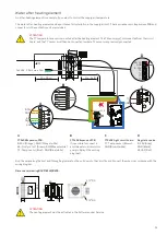
The water after-heating element can be purchased for installation in the supply air duct. The required sensors, Expansions PCB and
connectors to the ventilation unit are included.
Run the wires along the duct and through a grommet on the unit down to the circuit board. Connect the wires in accordance with the
wiring diagram.
Dimensional drawing Ø125/Ø160/Ø200:
ATTENTION
The T7 temperature sensor is mounted after the heating element. The T2 sensor must disconnected from the circuit
board, and the T7 sensor must then be connected to where T2 sensor was previously connected.
A
CTS602 Expansion PCB:
0-10V (Orange) - GND (Orange/white)
B3: Frost protect. (Green) - GND (Green/white)
T9: Temp. sensor (Blue) - GND (Blue/white)
B
CTS602 Expansion PCB:
It is possible to connect a
possible external circulation
pump in Relay 9 (See wiring
diagram)
C
CTS602 Light circuit board:
T7: Temp. sensor (Brown) -
GND (Brown/white)
D
Regulation valve:
0-10V (Grey)
GND (Black)
24VAC (Red)
ATTENTION
The heating element must be activated in the Software under Service.
T7
1x230V ~ 50 Hz max. 16A
24VAC
GND
0-10V
T9
T9
T7
T7
Min. 50 cm
T7
Min. 2 x Ø
CTS602 Light
T2
T9
B3
D
C
B
A
R9
R10
R8
R7
GND
T7
B3
GND
0-10V
GND
GND
T9
Expansion PCB
83
310
440
Ø
238
22
32
31
300
1/2" RG
1/2" RG


