Nikon HVBTR-1200 Instructions For Use Manual Download Page 29

En

Symbol for separate collection applicable in European countries

This symbol indicates that this product is to be collected separately.
The following apply only to users in European countries.
• This product is designated for separate collection at an appropriate 

collection point. Do not dispose of as household waste.

• For more information, contact the retailer or the local authorities in 

charge of waste management.

De

Symbol für getrennte Wertstoff-/Schadstoffsammlung in europäischen Ländern

Dieses Symbol zeigt an, dass dieses Produkt separat entsorgt werden 
muss.
Folgendes gilt für Verbraucher in europäischen Ländern:
• Dieses Produkt darf nur separat an einer geeigneten Sammelstelle 

entsorgt werden. Eine Entsorgung im Hausmüll ist unzulässig.

•  Wenden Sie sich für nähere Informationen bitte an Ihren Händler oder 

die örtlich für Abfallentsorgung zuständigen Behörden.

Fr

Symbole pour la collecte sélective applicable aux pays européens 

Ce symbole indique que ce produit doit être collecté séparément.
Les mesures suivantes concernent uniquement les utilisateurs euro-
péens.
•  Ce produit doit être jeté séparément dans un point de collecte appro-

prié. Ne jetez pas ce produit dans une poubelle réservée aux ordures 
ménagères.

•  Pour plus d’information, contactez le détaillant ou les autorités locales 

responsables de la gestion des ordures.

Es

Símbolo para recogida separada aplicable en países Europeos

Este símbolo indica que este producto se recogerá por separado.
Lo siguiente sólo se aplicará en países Europeos.
•  Este producto ha sido designado para su recogida en un punto de al-

macenamiento apropiado. No lo tire como un deshecho doméstico.

•  Para más información, contacte con el vendedor o autoridades locales 

al cargo de la gestión de residuos.

Nl

Symbool voor gescheiden inzameling zoals dat wordt gebruikt in Europese landen

Dit symbool betekent dat dit product apart moet worden ingezameld.
Het volgende is alleen van toepassing op gebruikers in Europa
•  Dit product dient gescheiden ingezameld te worden op een daartoe 

bestemd inzamelpunt. Niet wegwerpen bij het normale huisvuil.

•  Neem voor meer informatie contact op met het verkooppunt, of met 

de lokale instantie die verantwoordelijk is voor het verwerken van 
afval.

Dk

Symbol for special bortskaffelse af denne type produkter i de europæiske lande

Dette symbol angiver, at dette produkt skal bortskaffes specielt.
Det efterfølgende er kun til forbrugere i de europæiske lande.
• Dette produkt skal bortskaffes på fx en genbrugsplads el .lign. Det 

må ikke smides væk som normalt husholdningsaffald.

• For yderligere information kontakt din forhandler eller de lokale 

myndigheder, som fx teknisk forvaltning.

Pt

Símbolo para recolha de resíduos em separado utilizado nos países Europeus 

Este símbolo indica que este produto é para ser recolhido separada-
mente.
Esta norma aplica-se só para os utilizadores nos países Europeus.
• Este produto está designado para recolha de resíduos em separado num 

recipiente apropriado.  Não deitar no caixote do lixo doméstico.

• Para mais informações, contactar o revendedor ou as autoridades 

locais responsáveis pela gestão dos resíduos.

It

Simbolo per la raccolta differenziata applicabile nei paesi europei

Questo simbolo indica che il prodotto va smaltito separatamente.
La normativa che segue si applica soltanto agli utenti dei paesi europei.
• Il prodotto è designato per lo smaltimento separato negli appositi 

punti di raccolta. Non gettare insieme ai rifi uti domestici.

• Per maggiori informazioni, consultare il rivenditore o gli enti locali 

incaricati della gestione dei rifi uti.

No

Symbol for kildesortering i europeiske land

Dette symbolet indikerer at produktet skal kildesorteres.
De nedenstående punktene gjelder for alle europeiske brukere.
•  Dette produktet skal kildesorteres og innleveres til dedikerte innsam-

lingspunkter. Må ikke kastes med normalt husholdningsavfall.

•  For mer informasjon, ta kontakt med din forhandler eller lokale myn-

digheter.

Se

Symbol för separat upphämtning i euopeiska länder

Den här symbolen anger att produkten måste hämtas separat.
Följande gäller bara användare i europeiska länder.
• Den här produkten är avsedd för separat upphämtning vid ett lämpligt 

uppsamlingsställe. Produkten får inte kastas i hushållsavfall.

•  För mer information, kontakta återförsäljaren eller de lokala myndig-

heter som ansvarar för avfallshantering.

Fi

Erillisen keräyksen merkki Euroopan maissa

Tämä merkki osoittaa, että tuote kerätään erikseen.
Seuraavat maininnat koskevat vain eurooppalaisia käyttäjiä.
• Tämä tuote kerätään erikseen asianmukaisista keräyspisteistä. Älä 

hävitä tuotetta talousjätteiden mukana.

• Lisätietoja saat jälleenmyyjältä tai paikallisilta jätehuoltoviranomaisilta.

Ru

  Символ сортировки мусора, использующийся в европейских странах

Данный символ означает, что этот продукт должен 

утилизироваться отдельно от других.

Приведенная ниже информация касается только пользователей 

из стран Европы.

•  Данный продукт должен утилизироваться отдельно от других в 

соответствующих приемных пунктах. Не выбрасывайте данный 

продукт вместе с бытовым мусором.

•  Дополнительную информацию Вы можете получить у продавца 

или у местных властей, отвечающих за утилизацию мусора.

Gr

  Σύμβολο για την ξεχωριστή αποκομιδή απορριμμάτων στις Ευρωπαϊκές χώρες

Αυτ το σύμβολο υποδηλώνει τι η αποκομιδή αυτού του προϊντος 

πρέπει να γίνει ξεχωριστά.

Τα κάτωθι απευθύνονται μνο σε Ευρωπαίους χρήστες.

• Αυτ το προϊν είναι σχεδιασμένο έτσι ώστε να γίνεται η 

αποκομιδή του σε ειδικά σημεία. Μην το πετάτε μαζί με τα 

υπλοιπα απορρίμματα.

• Για περισστερες πληροφορίες, επικοινωνήστε με τον διανομέα 

του προϊντος ή με τις υπεύθυνες τοπικές αρχές για θέματα 

διαχείρισης απορριμμάτων.

Pl

  Symbol oznaczający segregowanie odpadów, stosowany w krajach Europy

Ten symbol oznacza, że produkt musi być wyrzucany oddzielnie.
Poniższe uwagi mają zastosowanie tylko dla użytkowników z Europy.
•  Ten produkt jest przeznaczony do oddzielnej utylizacji i powinien być 

dostarczony do odpowiedniego punktu zbierającego odpady.  Nie 
należy go wyrzucać z odpadami gospodarstwa domowego.

• Aby uzyskać więcej informacji, należy skontaktować się z 

przedstawicielem przedsiębiorstwa lub lokalnymi władzami 
odpowiedzialnymi za zarządzanie odpadami.

Hu

  Európai országokban érvénes “Elkülönített hulladékgyűjtés” jelzése

Ez a jelzés azt jelenti, hogy ezt a terméket elkülönítve kell gyűjteni.
Az alábbiak csak az európai országokban élő felhasználókra érvényes.
• Ezt a terméket a megfelelő hulladékgyűjtőhelyen, elkülönítve kell 

gyűjteni. Ne dobja ki háztartási hulladékként.

• További információkért forduljon a forgalmazóhoz, vagy a helyi 

hatóság hulladékgyűjtésért felelős részlegéhez.

Cz

  Symbol pro oddělený sběr odpadu platný v evropských zemích

Tento symbol znamená, že tento produkt se má odkládat odděleně.
Následující pokyny platí pro uživatele z evropských zemí.
•  Tento produkt se má odkládat na místě sběru k tomuto účelu určeném. 

Neodhazujte spolu s domácím odpadem.

• Více informací o způsobu zacházení s nebezpečným odpadem vám 

podá příslušná místní instituce.

Jp

䝬䞀䝱䝇䝕䛱䛐䛗䜑ᗣᲘ∸಴ืᅂ཭䛴䜻䝷䝠䝯䝢䞀䜳

䛙䛴䜻䝷䝠䝯䝢䞀䜳䛵ᮇ⿿ဗ䛒಴ื䛱ᅂ཭䛛䜒䛰䛗䜒䛶䛰䜏䛰䛊䛙䛮䜘
♟䛝䛬䛊䜄䛟䚯
ḗ㡧䛵ᮇ⿿ဗ䜘䝬䞀䝱䝇䝕 䟺㻨㻸䟻 䛭౐⏕䛟䜑ሔྙ䛱䛴䜅㐲⏕䛛䜒䜄䛟䚯

㻃 ᮇ⿿ဗ䛵ᣞᏽ䛛䜒䛥཭㞗ሔᡜ䛭಴ื䛱ᅂ཭䛛䜒䜑䜎䛌䛱ᏽ䜇䜏䜒䛬

䛊䜄䛟䚯 ᐓᗖ䜸䝣䛮䛝䛬ᗣᲘ䛝䛰䛊䛭䛕䛦䛛䛊䚯

㻃 リ⣵䛱䛪䛊䛬䛵㈅኉௥⌦ᗉ䜄䛥䛵ᆀᇡ䛴ᗣᲘ∸ฌ⌦ᶭ㛭䛱䛚㏻⤙

䛕䛦䛛䛊䚯

This symbol is provided for use in the People’s Republic of China, 
for environmental protection in the fi elds of electronic information 
products.

䛙䛴䝢䞀䜳䛵䚮 ୯ᅗ䛴䛐ᐂᵕ䛱ྡྷ䛗䛥䜈䛴䛭䚮 㞹Ꮔ᝗ሒ⿿ဗฦ㔕䛱
䛐䛗䜑⎌ሾಕ㆜䜘┘Ⓩ䛮䛝䛬䛊䜄䛟䚯

Summary of Contents for HVBTR-1200

Page 1: ...CNC Video Measuring System iNEXIV model VMA 2520 Instructions Hardware E163E 07 1 CF 1 E163EN01 ...

Page 2: ......

Page 3: ...any other system that you may be using in conjunction with this product such as a personal computer display etc Warning Symbol Used in This Manual Although Nikon products are designed to provide you with the utmost safety during use incorrect usage or disregard of the instructions can cause personal injury or property damage as well as voiding the terms of warranty For your safety read the instruc...

Page 4: ...15 kg This label on the stage reminds you of the following cautions The maximum mass that can be placed on the stage is 15 kg Never exceed the maximum permissible mass taking into consideration not only the mass of the workpiece but also the mass of the clamps etc Exceeding the maximum permissible mass could cause the stage glass to break Symbol Explanation CAUTION 可動部が上昇します 手を触れないでください また 十分な可動空間...

Page 5: ...e front side of the lower head section This label reminds you of the following cautions Do not look directly at the laser beam red light intentionally for an extended period of time Doing so can damage your eyes Be sure to read the instruction manual for the VMA LAF35 for iNEXIV VMA Series carefully before using the system The instruction manual contains important safety information ...

Page 6: ...t may be running 4 Emergency stop In a case of emergency press the yellow STOP switch located on the top right of the joystick box The system stops immediately To recover from an emergency stop turn the power off clear the condition that necessitated the emergency stop and then restart the system 5 Mass of the workpiece The maximum mass that may be placed on the stage is 15 kg Never exceed the max...

Page 7: ...rounded three conductor outlet Improper grounding can result in electric shock or abnormal operation Always be sure to turn OFF all of the power switches before plugging in the power cords 2 Do not touch moving parts Do not touch any moving parts as these parts can trap your hands or fingers 3 Cautions concerning heat from the controller Note that the internal parts of the controller are extremely...

Page 8: ... obstruct the ventilation openings on the front of the controller Make sure that the main body and the side of the measurement stand are at least 20 cm away from the nearest wall When setting up a personal computer rack or other equipment next to the main body or the side of the measurement stand also provide a space of at least 20 cm Failure to follow this instruction may lead to the risk of coll...

Page 9: ...e the device driver may not be set correctly The iNEXIV software can be used only when the appropriate driver is detected and installed when the cable is connected for the first time according to the instructions provided during the software installation 7 Cleaning finished surfaces and plastic components We recommend using a silicone cloth to clean finished surfaces and plastic components If a su...

Page 10: ...1 5 Controller 5 1 6 Joystick Box 6 Chapter II System Setup 7 2 1 Warnings 7 2 2 Required Tools 7 2 3 Setup Procedures 8 Chapter III Operation 14 3 1 Turning the Power On and Off 14 3 2 Cleaning 14 3 3 Lubricating the System 14 Chapter IV Performance and Specifications 15 4 1 Style 15 4 2 Digital Read Out 15 4 3 Motion Control 15 4 4 Sections 16 4 5 Measurement Accuracy 17 4 6 Operating Conditions...

Page 11: ... 1 Chapter I Names of Parts and Their Functions 1 1 General Main body and stage section Measurement stand Controller Rubber vibration isolator Host computer Joystick box Display ...

Page 12: ...s O v e r c o n c e n t r a t i o n o f ma s s o n s t a g e Ma x i m u mp e r mi s s i b l e ma s s 1 5 k g 最大許容積載質量 1 5 k g ス テ ー ジ ガ ラ ス が 破損 す る 恐れが あ り ま す ストロークエンドセンサ間 ストロークエンドセンサまで C L A S S 1 L A S E R P R O D U C T Distance between stroke end sensors To the stroke end sensors ...

Page 13: ... of Stage 20 M6深10 測定範囲 Maximum permissible mass 15 kg The weight of clamps used for securing the workpiece should be taken into consideration 20 M6 Depth 10 Measurement area 250 Measurement area 200 Measurement area ...

Page 14: ... 4 1 4 System Layout ホストPC ラック 測定台外形 本体外形 床支持位置 脚直径 60 Outline of measurement stand Outline of main unit Leg position leg diameter 60 Host computer rack ...

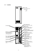
Page 15: ... connector on the joystick unit with the provided cable CAMERA connector Connect the CAMERA cable from the main body to this connector IEEE1394 connector Connect to the IEEE1394 connector on the host PC with the provided cable USB connector Connect to the USB connector on the host PC with the provided cable ETHERNET connector Not used in normal use MOTOR connector Connect to the MOTOR connector on...

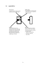
Page 16: ... Soft keys Each soft key can be set with a function from the host computer The soft keys can be set with the following functions Joystick slow drive mode Clamping of each axis Zoom factor Joystick Use the joystick to move the workpiece in the X and Y directions or to move the vertical mover in the Z direction for focusing The drive speed changes according to the tilting angle of the joystick and t...

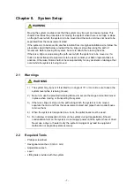
Page 17: ...ity for any accidents or damage that occur while the system is being moved 2 1 Warnings WARNING 1 The system may tip over if it is tilted to an angle of 15 or more Be sure to keep the system level while it is being moved 2 Be sure to use the provided retaining fixtures to secure the stage and vertical mover in place when moving or transporting the system 3 If there is a ridge or slope on the path ...

Page 18: ...ormed using a fork lift or by four or more persons In this step adjust the positions of the rubber vibration isolators carefully so that the 3 adjustable legs of the main unit are located exactly at the centers of the isolators After the main unit is positioned properly detach the 4 lifting bars and insert the provided caps into the holes installation of caps is not mandatory 4 Move the system to ...

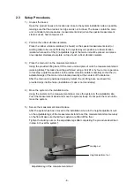
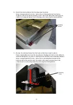
Page 19: ...ve the retaining fixtures from the Z axis vertical mover see the photo Place an appropriate cover over the top surface of the stage so that it is not scratched or otherwise damaged by any bolts or retaining fixtures that fall or are accidentally dropped Using a hexagonal wrench 3 mm remove the red retaining fixture located on the bottom section of the vertical mover Be careful not to apply excessi...

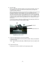
Page 20: ...table legs on the main unit for fine adjustment After all adjustments have been completed be sure to tighten the locking nuts on all of the adjustable legs on the measurement stand and the main unit In this process make sure that all four adjustable legs of the measurement stand are in secure contact with the floor and that the stand is stable Adjustable leg of the main unit 9 Connect the cables b...

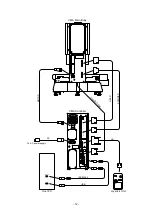
Page 21: ... may ask you to check the status indicator LEDs on the rear panel of the controller 12 Connect the cables between the controller and host computer Turn off the power switch of the controller Connect the USB cable and IEEE1394 cable to the host computer referring to the illustration on the following page Note Keep the power switch of the controller turned off until an instruction to turn on the swi...

Page 22: ...V D CA ME RA IEEE1 3 9 4 RS 2 3 2 C USB D Bo o t Eth e rn e t CASE M O TO R HEAD ENCO DER STO P S1 S2 S3 VM A J S IEEE1394 IEEE1394 MOTOR J S HEAD C A M E R A L I N K USB ENCODER AC Joystick Unit Host PC VMA Controller VMA Main Body USB To AC power supply ...

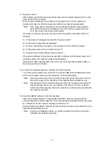
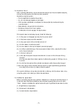
Page 23: ...legs of the measurement stand in firm contact with the floor and is the stand stable 7 Is the main unit level 8 In the case the special measurement stand is not used is the table used strong enough It is recommended that a table capable of withstanding weight of 1 000 kg or more be used 9 Are the floor strength and floor vibration parameters within the specified ranges 10 Are the special rubber vi...

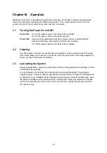
Page 24: ...g Use this system in as clean an environment as possible in order to prevent dust and grease from accumulating on the system In particular clean the guide faces of the stage regularly to make sure they remain clean at all times 3 3 Lubricating the System Supply Sukuwaral M 1 grease manufactured by Riken to the guide faces of the stage to clean and lubricate the surfaces It is not necessary to lubr...

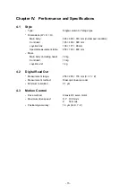
Page 25: ...100 177 98 mm Special measurement table 650 700 600 mm Mass Main body including head 72 kg Controller 13 kg Joystick unit 1 kg 4 2 Digital Read Out Measurement range 255 205 155 mm X Y Z Measurement method Diascopic linear encoder Minimum resolution 0 1 µm 4 3 Motion Control Drive method All axis DC servo motor Maximum drive speed X Y 100 mm s Z 50 mm s Positioning accuracy 1 0 µm for X Y Z ...

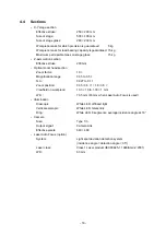
Page 26: ...0 Magnification range 0 35 to 3 5 N A 0 027 to 0 11 Zoom position 0 35 0 6 1 1 8 3 5 Viewfield on workpiece 13 3 10 to 1 33 1 mm W D 73 5 mm 63 mm when Laser Auto Focus is used Illumination Diascopic White LED diffused light Vertical episcopic White LED telecentric Ring White LED 8 segments average incidence angle at 18 Camera Size Type 1 3 Output signal Camera Link Effective pixels 640 480 Laser ...

Page 27: ... a laser scale Maximum permissible indication error for single axis measurement MPEE1 3 L 50µm 4 6 Operating Conditions Operating environment Temperature 10 C to 35 C Humidity 70 max Altitude 2000 m max Pollution Degree 2 Indoor use only Environment in which accuracy is guaranteed Temperature 20 C 0 5 K Floor strength Average load bearing capacity Must be able to bear the mass on the total floor s...

Page 28: ... rated at 250 V AC minimum 4 8 Applicable Electrical Safety Standards In a 100 V 120 V region This product meets FCC 15B Class A requirements This equipment has been tested and found to comply with the limits for a Class A digital device pursuant to Part 15 of the FCC Rules These limits are designed to provide reasonable protection against harmful interference when the equipment is operated in a c...

Page 29: ...i europeiske land Dette symbolet indikerer at produktet skal kildesorteres De nedenstående punktene gjelder for alle europeiske brukere Dette produktet skal kildesorteres og innleveres til dedikerte innsam lingspunkter Må ikke kastes med normalt husholdningsavfall For mer informasjon ta kontakt med din forhandler eller lokale myn digheter Se Symbol för separat upphämtning i euopeiska länder Den hä...

Page 30: ...2 3 Marunouchi 3 chome Chiyoda ku Tokyo 100 8331 Japan Sales Dept Bio Science Division Instruments Company Parale Mitsui Bldg 8 Higashida cho Kawasaki ku Kawasaki Kanagawa 210 0005 Japan Tel 81 44 223 2167 Fax 81 44 223 2182 Sales Dept Industrial Instruments Division Instruments Company Parale Mitsui Bldg 8 Higashida cho Kawasaki ku Kawasaki Kanagawa 210 0005 Japan Tel 81 44 223 2175 Fax 81 44 223...

Reviews: