JAA78851-R.3617.A
- L46 ・ AF-S DX17-55/2.8G -
H
L
Sandard
H:L=
100
:
200
~
200
:
100
(
50
%
±17.3
%)
ADJUSTMENT OF MR DUTY
●In case of replacing the main PCB, SWM unit and MR encoder unit, be sure to make adjustments.
●In case of replacing the main PCB, be sure to perform [READING AND REWRITING OF EEPROM DATA.] then
[3.WRITING THE FIXED VALUES.]
How to adjust
①
Make sure that the electric current and voltage of the connected rated voltage power supply are set to the set
values. Then, turn the rated voltage power supply ON for the contacts A and F.
②
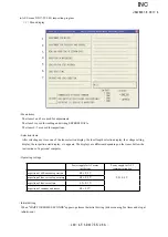
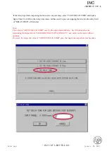
Select "MR DUTY ADJUSTMENT" in the menu of the AF-S DX-zoom 17-55 inspection program.
③
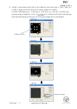
The display for checking whether the fixed values are written in EEPROM appears. Select a proper item.
④
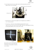
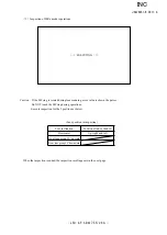
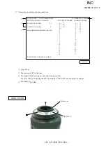
According to the instructions on the screen, rotate the MF ring from the near distance to the infinity to the near
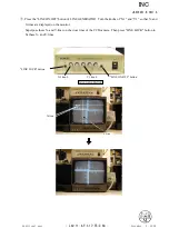
distance direction slowly by hand. Make sure that the waveform on the oscilloscope has duty 50% and then stop
the MF ring at the near distance end.
● Setting of oscilloscope
V/Div
(
CH1
)
:
5V
V/Div
(
CH2
)
:
5V
Coupling
:
DC
Time/Div
:
5 m Sec
Trigger Mode
:
NORMAL
Trigger Coupling
:
DC
Trigger Source
:
CH
1
Trigger Position
:
+4 div
Trigger Type
:
EDGE
Trigger Level
:
2.5 V
⑤
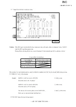
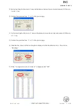
According to the instructions on the screen, rotate the MF ring from the near distance to the infinity direction
slowly by hand. Make sure that the waveform on the oscilloscope has duty 50% and then stop the MF ring at the
infinity end.
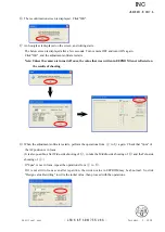
Note
:
In case the waveform from infinity to close distance position or vice versa does not have duty 50%, repeat
"INSPECTION AND ADJUSTMENT OF THE MR ENCODER OUTPUT WAVEFORM" on Page L20.
C H 1 = 5 V C H 2 = 5 V 5 m s / d i v
D C 1 0 : 1 D C 1 0 : 1
NORM 200KS/s
INC


