


Height Rider/SP Series
Operating & Safety Instructions
English/USA – 01/18
Original instructions
22
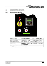
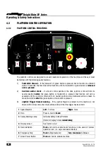
4.1.2
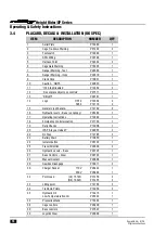
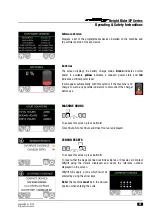
PLATFORM
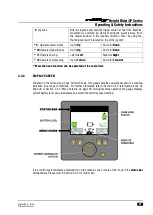
CAGE DISPLAY UNIT:
- Mounted in the Platform Control Station, this screen receives signals from the
PLC to provide a warning indication to the operator for a range of functions. Refer to Section 4.3.2 for
further details.
LOAD SENSING CONSOLE (SiOPS
TM
): -
This machine incorporates a load sensing console that
senses if the operator has been pushed or has fallen against the console. If the load applied to the front
of the console is greater than the pre-determined amount, the footswitch will be disabled to increase
operator safety and reduce the possibility of sustained involuntary operation of the cage controls. For
further information refer to Section 4.3.6.
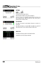
4.1.3
FUSES
Chassis
Under
front
cover
250A
Fuse (isolator)
Module Box 3 (NE)
(Refer to HR12 MK2 Service Manual for fuse layout diagram)
Under
rear
cover
125A x 3
Fuses on Drive control tray (Motor controllers)
Module Box 2
(Drive control tray)
(Refer to HR12 MK2 Service Manual for fuse layout diagram)
Module Box 3 (LE)
(Drive control tray)
(Refer to HR12 MK2 Service Manual for fuse layout diagram)
Ground Control Station
Module Box 1
(Refer to HR12 MK2 Service Manual for fuse layout diagram)
Platform Control Station
5A
blade fuse behind Control Panel
2 x 3A
blade fuses behind Control Panel
Summary of Contents for HR 12
Page 77: ......