background image

III. OPERATION

     FH94G

Printed in the USA © 2020 Nieco Corporation

All Rights Reserved P/N  99107

7950 Cameron Drive 

Windsor, CA 95492 

Phone: 707.284.7100 

Fax: 707.284.7430

[email protected] 

Revision History:

Date

Notes

Revision

A

Summary of Contents for FH94 Gas

Page 1: ...als and the flow of ventilation air must not be obstructed Operating personnel must not perform any maintenance or repair functions Contact your Nieco Authorized Service Agent for service or repair Mo...

Page 2: ...nd a contact separation must be included in the fixed wiring 7 It is recommended that walls et cetera in the proximity of the appliance be made of non combustible material if not they must be clad wit...

Page 3: ...J Pre Operation Check 9 III Operation 10 21 Power Switch Controls 10 Touch Screen Controls 11 Lighting Procedures 12 Troubleshooting Ignition Failure 13 Manual Ignition Guide 14 Shutdown Procedures 15...

Page 4: ...ims are the responsibility of the purchaser and ARE NOT covered under warranty The warranty does not extend to Damages caused in shipment or damage as a result of improper use Installation of electric...

Page 5: ...t Safety Information Throughout this manual you will find the following safety words and symbols that signify important safety issues with regards to operating or maintaining the equipment WARNING GEN...

Page 6: ...eference to the use of chemical products The Nieco Corporation does not endorse the use of any particular cleaning degreasing agent Use only those chemicals that are approved for use in your kitchen T...

Page 7: ...placed on a level surface D Hood Requirements This appliance must be installed under a ventilation hood of adequate size Do not obstruct the flow of combustion and ventilation air An adequate air supp...

Page 8: ...rning to consumers in California restaurants G Installing Gas Appliance Connectors and Flexible Gas Lines Correctly For safety in the kitchen area and to insure maximum service life it is vitally impo...

Page 9: ...upplied to secure the installation For proper attachment to the broiler use the supplied hardware to attach the device to the holes in the broiler stand NOTE If disconnection of the restraint is neces...

Page 10: ...takes approximately 30 45 seconds to power on after main power switch has been turned on Main On Off Switch is used to power the broiler on or off Touch Screen Control Panel Controls all operation of...

Page 11: ...elt Lane 2 is the Right Belt Recipe Name Select Recipe Tap Semi circles to select recipe for each lane Temp Bubble Green light indicates ready to cook REV hold down to reverse belt Manager Settings Ac...

Page 12: ...omatic ignition When the chamber is turned on from the Touch Screen Control Panel a spark ignitor turns on with the flow of gas Gas then flows to all of the burners NORMAL IGNITION PRE LIGHTING PREPAR...

Page 13: ...times If the broiler does not light after the third attempt the IGNITION FAILURE LIGHT will flash on the home screen indicating the affected Chamber s Turn Chamber OFF from the Touch Screen Control P...

Page 14: ...ol Panel takes approximately 30 45 seconds to power on after Main Power Switch has been turned on 3 Use Touch Screen Control to turn on cooking chamber 4 Hold a lighter match to the Upper Burner on th...

Page 15: ...UTION FOR YOUR SAFETY Do not store or use gasoline or other flammable vapors or liquids in the vicinity of this or any other appliance 15 CAUTION FOR YOUR SAFETY In the event of a prolonged power fail...

Page 16: ...r Wait 30 45 Seconds for Touch Screen Control to Power On Touch Power to Turn Cooking Chamber On Touch Toggle Switch To Turn On or Off POWER TIPS Main On Off Switch is used to power the broiler on or...

Page 17: ...g a Recipe Click next recipe semi circle to toggle and select the recipe for each Belt Lane Lane 1 is the Left Belt Lane 2 is the Right Belt Touch to Toggle Recipe Selection For Left Belt Touch to Tog...

Page 18: ...to access Manager Settings Screen Password 123 Use the Manager Settings Control Screen to access monitor and set broiler temperature settings and add or adjust recipe settings 2 1 2 1 1 Set to 785 F...

Page 19: ...ond increments as required Select Save to confirm new recipe setting then touch to return to the Manager Settings Screen Select Lane 1 Left 2 Right Select Recipe Select Product Recipe to adjust eg WHO...

Page 20: ...just Recipe Increase or decrease belt speed time in 5 second increments as required Select Save to confirm new recipe setting then touch to return to the Manager Settings Screen Belt Speed Time is dis...

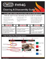
Page 21: ...You can access a visual guide to the cleaning process from the touch screen control home screen The images reflect the same process contained in this manual and in the FH94 cleaning chart poster Clea...

Page 22: ...tion of the part When to clean the part Picture of the part to be removed and cleaned How to remove and clean the parts The tools needed to clean the part The name of the part to be cleaned Every 4 Ho...

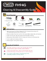
Page 23: ...proved cleaning solutions 6 Allow all parts to air dry after cleaning Tools Needed This Stop sign shows a step in the procedure that must be followed exactly or personal safety could be affected This...

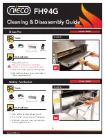
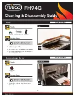
Page 24: ...se and sanitize in the 3 compartment sink Meat Guides Feed End Instructions Clean Every 4 hours Tools 3 Compartment Sink Scrub Pad 1 1 Slide the feeder cover towards you until it comes off 2 Wash with...

Page 25: ...tment sink DO NOT lift the feeder base by the feeder bar or the chains This will damage the feeder base REASSEMBLY Pull the release pin and place feeder base in position Feed End 1 Lift and remove 2 W...

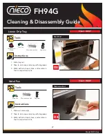
Page 26: ...compartment sink Feed End Instructions Tools Heat Resistant Gloves Heat Resistant Gloves Scrub Pad Scrub Pad Degreaser Degreaser 3 Compartment Sink 3 Compartment Sink 1 Slide holding pan bracket up an...

Page 27: ...rinse and sanitize in the 3 compartment sink Feed End Instructions Tools Heat Resistant Gloves Scrub Pad Degreaser 3 Compartment Sink 1 Slide out and empty 2 Take to sink area and spray with degreaser...

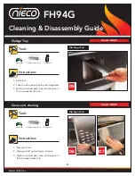
Page 28: ...th scrub pad rinse and sanitize in the 3 compartment sink Discharge End Instructions Tools Scrub Pad Scrub Pad Degreaser Degreaser 3 Compartment Sink 3 Compartment Sink 1 Remove Cover 2 Swing and lift...

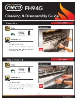
Page 29: ...sh with scrub pad rinse and sanitize in the 3 compartment sink Instructions Tools Scrub Pad Scrub Pad Degreaser Degreaser 3 Compartment Sink 3 Compartment Sink Discharge End 1 Lift tray up and out 2 T...

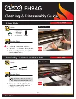
Page 30: ...h with scrub pad rinse and sanitize in the 3 compartment sink Discharge End Instructions Tools 1 Remove Carbon Build up from shafts and belts with supplied cleaning tools and brushes or equivalent Dis...

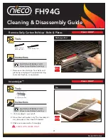
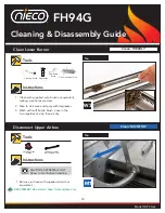
Page 31: ...equivalent Instructions Tools Top 1 Lift Incendalyst up and off 2 Rinse clean with water only The Incendalyst may be soaked then rinsed if needed 3 Shake out excess water thoroughly CLEAN WITH WATER O...

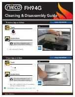
Page 32: ...sh with scrub pad rinse and sanitize in the 3 compartment sink Tools Instructions Top W1 Feed End W2 1 Open latch then lift Lower burners up then out Instructions Tools Heat Resistant Gloves Scrub Pad...

Page 33: ...ons Tools 1 Clean with supplied wire brush or equivalent making sure holes are clear 2 Take to sink area and spray with degreaser 3 Wash with soft bristle brush rinse in the 3 compartment sink then ai...

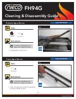
Page 34: ...op Instructions Instructions Tools Tools Heat Resistant Gloves 1 Clean with supplied wire brush or equivalent making sure holes are clear REASSEMBLY Reinstall air hose hand tighten only M2 M3 CAUTION...

Page 35: ...r up and out 1 Clean with supplied wire brush or equivalent making sure holes are clear Top Top Instructions Instructions Tools Tools Heat Resistant Gloves M4 M5 CAUTION EXTREMELY HOT Allow to cool be...

Page 36: ...ION FH94G Printed in the USA 2020 Nieco Corporation All Rights Reserved P N 99107 7950 Cameron Drive Windsor CA 95492 Phone 707 284 7100 Fax 707 284 7430 service nieco com Revision History Date Notes...

Reviews: