


4 - 29
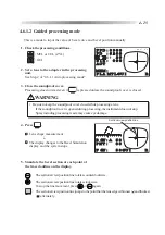
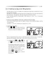
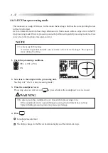
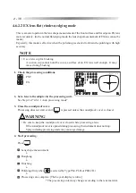
4.6.1.3 Guided processing mode (Tilting function)
The tilting function of bevel is available in the guided processing mode, in which the bevel curve
can be specified manually.
If the difference in width between the edge thickest point and thinnest point is extreme, the mounted lens
does not look nice. The appearance of the lens will get better if the bevel is tilted.
To use the tilting function, set the parameter “TILT Function” to “Exec”. See “5.2 Parameter
Settings” (p.5-2).
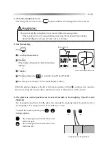
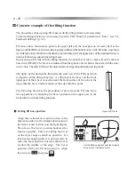
1. Select processing conditions, chuck a lens, and measure the lens shape.
After the lens shape measurement, the display changes to the simulation display, and the
instrument stops.
See Steps 1 - 5 of “4.6.1.2 Guided processing mode” (p. 4-25).
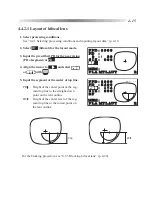
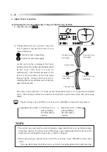
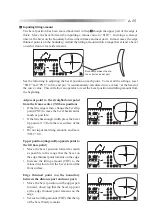
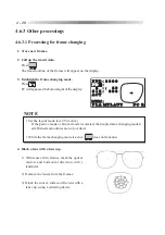
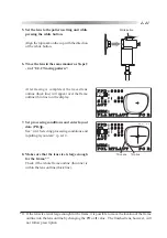
2. Adjust the bevel position.
1) Press
or
to move the sectional view
position line to the base position, and check
the bevel sectional view at that point.
The most appropriate tilt base position is the thinnest point of the lens edge, or a diagonally-
opposite point (through the frame center) to where the bevel tip point is to be moved.
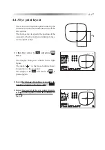
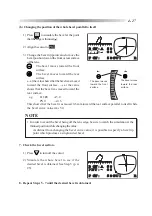
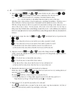
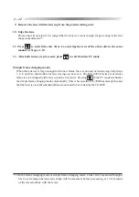
2) Align the cursor to
TILT
with
or
, and
press
to determine the tilt base position.
The tilt base position mark (
F
) will move
to the end of the sectional view position line.
After that, the line will automatically skip
to the diagonally-opposite point.
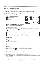
If the value is already input at “TILT”,
pressing
resets the value to 0.0.
In this case, press
again to set the tilt
base position.
ޓ
ޓ
ޓ
ޓ㧚
ޓ㧚
ޓ㧚
ޓ㧚
㧮%48㧦㧭ޓ㧠㧟
㧼㧺㨀㧦ޓޓ㧜㧜ޓޓޓޓޓޓޓޓ
㨀㧵㧸㨀㧦ޓ
ޓ
㧜㧜ޓ
㧲%48㧦ޓޓ㧡㧜㧳㨁㧵ޓޓޓޓ㧾
ޓ
ޓ
ޓ
ޓ㧚
ޓ㧚
ޓ㧚
ޓ㧚
㧮%48㧦㧭ޓ㧠㧟
㧼㧺㨀㧦ޓޓ㧜㧜ޓޓޓޓޓޓޓޓ
㨀㧵㧸㨀
㧦ޓ
ޓ
㧜㧜ޓ
㧲%48㧦ޓޓ㧡㧜㧳㨁㧵ޓޓޓޓ㧾
Summary of Contents for LE-9000LX
Page 1: ...PATTERNLESS EDGER Model LE 9000LX OPERATOR SMANUAL ...
Page 17: ...2 9 Top view or or ...
Page 19: ...2 11 ...
Page 145: ......


