background image

3

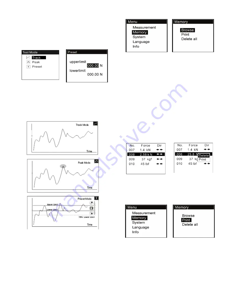
You can also select the mode under the Measurement menu in 
the Test Mode sub-menu. See Fig. 3-3(a)

If the Preset is selected, a new screen will pop up where you can 
set the Upper and Lower limits. See Fig 3-3(b)

Press ZERO to adjust the number and press MODE to move to 
the next digit.

                        Fig. 3-3(a)                   Fig. 3-3(b)  
Note: 
1) The upper limit can not exceed 110% capacity of the force 
gauge.

2) The lower limit must not be less than 10% of capacity.

3) The upper limit must exceed the lower limit

Fig. 3-4

4. SAVING THE MEASURED VALUE

Measured results can be stored in the force gauge’s memory. You 
can review or print the stored data at a later time.

At the home screen press the LOG key to store a value. The stor-
age icon will be displayed.

The data stored is the current displayed force value in Track and 
Preset modes. In Peak mode it is the peak value shown on the 
display.

4.1 Memory

Fig. 4-1

Memory menu contains three submenus: Browse, Print, Delete 
all, as shown in Fig. 4-1.

You can browse stored data or print all the data via the 
FG-PRINTER mini-printer (sold separately). You may also delete 
all the records in the Delete all sub-menu.

4.2 Browse
In the Browse sub-menu. The data in memory can be reviewed in 
the order saved which is oldest to newest. See Fig. 4-2(a)

Press ZERO/UP or MODE/DOWN to scroll.

Press MENU. A small window will pop out. Here you can select 
Delete or Print. See Fig. 4-2(b).

If you select Delete, a confirm window will appear asking you to 
confirm. Press MENU to confirm or LOG to exit.

Fig. 4-2(a)                       Fig. 4-2(b)

4.3 Print
You can print the data in memory. Enter Print. (Fig. 4-3) Choose 
Selected or All.

Fig. 4-3

If Selected is chosen, the total Range of available data points will 
be indicated. Adjust the value points to be printed to the right of  
Select. Fig. 4-3(a)

If All is selected, a confirm window will appear asking you to con-
firm. See Fig. 4-3(b).

Summary of Contents for FG-3000R-S

Page 1: ...s Do not use damaged clamp Measure in line tension and compression forces only DO NOT attempt to measure forces at an angle to the measuring shaft damage to load cell and or shaft may result Do not attempt to repair or alter this instrument Warranty will be voided and damage to the unit may result Use and store within the stated temperature and humidity ranges or damage and failure may result When...

Page 2: ...PARATION 2 1 Confirm the model This series force gauge has 5 ranges available each model corre sponding to the capacity and resolution shown on the last page of this manual Select the appropriate model you need before use 3 SETUP 3 1 Measurement The Measurement menu contains the Unit of measure and Mea surement Mode sub menus as shown in Fig 3 1 Fig 3 1 3 2 Select Units The measuring units can be ...

Page 3: ...s the peak value shown on the display 4 1 Memory Fig 4 1 Memory menu contains three submenus Browse Print Delete all as shown in Fig 4 1 You can browse stored data or print all the data via the FG PRINTER mini printer sold separately You may also delete all the records in the Delete all sub menu 4 2 Browse In the Browse sub menu The data in memory can be reviewed in the order saved which is oldest...

Page 4: ... keypad un derneath while Reverse will allow the display to be up right with the keypad above Fig 5 1 b Fig 5 1 b 5 2 Auto Power The FG 3000R has an automatic power off function With Auto Power on if there is no operation performed within five minutes it will power off automatically Fig 5 2 Fig 5 2 5 3 Backlight The backlight can be set to turn on or off See Fig 5 3 Choosing the backlight to be of...

Page 5: ...after a period of usage It is recommended to send the force gauge to a specialized test ing organization for calibration If you have standard force weights or other standard load and a test stand you may utilize this function and procedure to calbrate the sensor Fig 5 6 a 1 Mount the force gauge 2 Use the tare by use of the ZERO key 3 Enter Calibration sub menu as in Fig 5 6 a The calibration inte...

Page 6: ... bits Stop bit 1bit Parity None Baud rate 38400 Fig 8 2 8 2 Setpoint Output Two NPN open collector setpoint outputs are available The internal circuit of the setpoint output is shown as Fig 8 2 Pin7 with Pin6 will be connected when an overload alarm occurs In Preset Mode Pin7 to Pin6 is connected when the measured value exceeds the upper limit Pin4 to Pin6 is connected when the measured value pass...

Page 7: ...ty 1000 1 100 220 Resolution 1 0 001 0 01 0 01 FG 3000R 5 Capacity 5000 5 500 1100 Resolution 1 0 001 0 1 1 FG 3000R 10 Capacity 10 1000 2250 Resolution 0 01 1 1 FG 3000R 20 Capacity 20 2000 4500 Resolution 0 01 1 1 FG 3000R 50 Capacity 50 0 5000 11 Resolution 0 01 1 0 01 ...

Page 8: ...SEALS USA Inc Instruments Division Tel 630 924 7138 Email support seals usa com ...

Reviews: