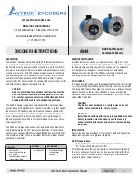


AV44 Solid Shaft Incremental Encoder
AV44
1
www.avtronencoders.com
Nidec Industrial Solutions
243 Tuxedo Avenue | Cleveland, Ohio 44131
+1 216-642-1230
Solid Shaft Magnetic
Incremental Encoder
ENCODER INSTRUCTIONS
Rev: 003
DESCRIPTION
The Avtron™ Encoders model AV44 Solid Shaft Incremental Encoder
is a speed and position incremental transducer (also known as a
tachometer or pulse generator). When mounted to a motor or machine,
its output is directly proportional to relative shaft position (pulse count)
or speed (pulse rate). The AV44 employs magnetic sensing technology
and operates down to zero speed, and it can be used for both control
and instrumentation applications. The AV44 encoder offers 2-phase
outputs (A, B) 90° apart for direction sensing, with complements (/A, /B)
and with marker pulse and complement (Z, /Z).
CAUTION
AV44 is not certified for hazardous locations. Do not utilize
AV44 in hazardous locations which require ATEX, UL, CUL,
CSA, or other explosion protection certification. Use Avtron
Encoders XR or XP models for hazardous applications.
The AV44’s housing is rugged cast aluminum with a durable powder
coat finish, and the electronics are fully encapsulated to protect against
the elements. The AV44 is a flange-mounted encoder available with
industry standard “B10 Euro-flange” or “PY” flange/shaft configurations
or on a foot-mount bracket for coupling for use in a wide range of
industrial applications. AV44 is not recommended for pulley or chain
drive applications.
The AV44 has a diagnostic package that includes Adaptive Electronics
and red/orange/green LED for local status indication. A Fault-Check
output is also available. With this package the AV44 can maintain itself
and provide an alarm if there is a problem before the problem causes
unscheduled downtime.
ADAPTIVE ELECTRONICS
A perfect duty cycle consists of a waveform whose “high” and “low”
conditions are of the same duration (50%/50%). It is possible over time
for the duty cycle and edge separation to change due to component
drift, temperature changes, or mechanical wear. The Adaptive
Electronics extend the life of the AV44 by constantly monitoring and
correcting duty cycle and edge separation over time.
FAULT-CHECK
If the Adaptive Electronics reach their adjustment limit, the LED will turn
red. If selected the Fault-Check alarm will notify the drive and operator
of an impending failure. This output can occur before a failure, allowing
steps to be taken to replace the unit before it causes unscheduled
downtime. Fault-Check annunciation is available as an “alarm” output
option (Mod Code 068).
CAUTION
The AV44 is not considered as a safety device and is not
suitable for connection into a safety system.
WARNING:
Installation should be performed only by qualified personnel.
Safety precautions must be taken to ensure machinery
cannot rotate and all sources of power are removed during
installation
.
INSTALLATION
Refer to the back pages of these instructions for outline and mounting
dimensions, as well as wiring/pinout diagrams.
Shaft/Flange Options:
• “B10 Euroflange” with 11mm shaft with 4mm X 20mm key
• “PY” Flange with 5/16” shaft with flat
For reliable feedback the encoder requires a constant velocity ratio to
the motor, and as such must be driven by a positive drive rather than
a friction drive. The following means of coupling is acceptable when
properly installed: Direct Coupling.
INCLUDES
OPTIONAL
NOT INCLUDED
- AV44 Encoder
- 4mmx20mm feather key
(B10 version)
- Flange Mounting Hardware
- Thread-Locker (Blue)
- Foot Mount Kit
- Dial Indicator Gauge
- Caliper Gauge
- Coupling


