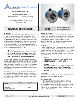
AV44 Solid Shaft Incremental Encoder
3
Rev: 003
CORRECTIVE ACTION FOR PHASE REVERSAL
If Encoder Direction is wrong:
1) Remove power.
2) Exchange wires on cable, either at encoder cable end, or at
speed controller end (but not both):
a.) Single Ended 2 Phase Wiring (see wiring diagram below)
Exchange A and B at the user end of the wires.
(/A & /B are not used)
b.) Differential 2 Phase Wiring (see wiring diagram below)
Exchange either A with /A in the phase A pair OR B with /B in
the phase B pair but NOT both.
3) Apply power.
4) Verify encoder feedback is correct, using hand rotation of shaft, or
jog mode of the speed controller.
Interconnecting cables specified in the wire selection chart are based on
typical applications. Refer to the “Wiring Diagrams” below for suggested
cable types. General electrical requirements are: stranded copper, 22
thru 16 gauge each twisted wire pair individually shielded with braid or
foil drain wire, 0.05 uF maximum total mutual or direct capacitance with
outer sheath insulator.
Our B37178 cable offers excellent noise performance, minimized power
supply loss and ultra-low capacitance for minimized signal loading. See
technical details on Spares & Accessories page.
Note: Maximum cable length (and line driver selection) is limited by
several factors: line driver protection, maximum RPM, PPR, output
voltage and cable capacitance. Line driver option “2” permits the
longest cable lengths (up to 300m at 45KHz). All AV44 line drivers
have full protection against external faults. These factors may dictate
maximum potential cable length.
FAULT-CHECK
After power-up and the rotor position is checked by the sensor, the Fault
Check LED will turn GREEN.
If the adaptive electronics reach their adjustment limit for any reason,
the Fault-Check alarm and LED will notify the drive and operator of an
impending failure. The LED will turn RED if the Adaptive Electronics
reach their adjustment limit. This output occurs before an actual
failure, allowing steps to be taken to replace the unit before it causes
unscheduled downtime.
If the alarm output and/or LED indicate a fault (RED):
If the alarm output and/or LED indicate a fault (RED) on a properly
mounted AV44, the encoder may be faulty and should be replaced.
An oscilloscope can also be used to verify proper output of the AV44
at the encoder connector itself and at the drive/controller cabinet. If
the outputs show large variations in the signals at steady speed (jitter
or “accordion effect”) this may be a sign of excess external magnetic
interference &/or the motor or shaft may be highly magnetized. Replace
any nearby magnetized material with non-magnetic material (aluminum,
stainless steel) (especially shafts). If the source of magnetic interference
cannot be eliminated, another encoder model may be required that
offers super-magnetic shielding such as Avtron Encoders HS45 (hollow
shaft) or AV45 (solid shaft).
If the LED is ORANGE (or blinking ORANGE):
This indicates that the outputs have shut off due to thermal overload.
The most likely cause is shorted outputs or undervoltage to the encoder.
Stop the system. Remove all output wires/connections
(A, /A, /B, B, Z, /Z). The LED should turn GREEN. If the LED does not turn
GREEN, the encoder is not receiving enough voltage at +V to properly
operate. Correct the input voltage problem. If the LED turns GREEN
once all outputs are disconnected, reconnect each output, one at a time,
monitoring for ORANGE LED. For partial/resistive short circuits, the LED
may take a few minutes to turn ORANGE. Once the shorted output(s)
are located, correct the shorting condition, and the encoder LED should
remain GREEN.
If equipped with the remote alarm option (Mod code 068), the /ALM
output will be asserted Low (~OV) whenever the LED is either RED or
ORANGE.
If the LED is OFF
,
but power is being applied to the encoder, check the output voltage level
at A,/A,B,/B. If all outputs are Low (~OV), the connections to +V and
COM are reversed. Swap connections bV and COM; the LED
should turn GREEN.


