


06
. Slightly loosen the travel limit mechanical stop screw and manually open
the door until it reaches the maximum
Opening
position (
fig. 28
) .
07
. Move the travel limit mechanical stop up against the carriage .
Then tighten the travel limit mechanical stop screw fully down (
fig. 29
) .
Note
– During normal operation the carriage stops a few centimetres
before the mechanical stop.
08
. To re-block the door, close it manually until it clicks firmly into place.
STEP 6
After installing all devices in the system – each in the position specified in STEP
4
– connect each device to the control unit as follows .
CAUTION!
– Incorrect connections can cause faults or hazards; there-
fore ensure that the specified connections are strictly observed.
01.
Use a screwdriver to loosen the screw on the control unit cover and
extract the cover (
fig. 30
), to access the terminals for electrical connec-
tions of the control unit .
02.
Use the same screwdriver to open the slots required for routing the elec-
tric cables (
fig.
31) from the various devices in the system .
03.
Then connect the electric wires of the system devices to the control unit
using the terminal board with five terminals (
fig. 32
) .
CAUTION – The section of electric cable connecting terminals 3
and 5 must only be removed if photocell installation is envisaged.
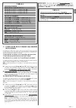
For correct connections, proceed as follows:
• To connect a pair of photocells with safety function
One or more pairs of photocells with a safety function must be installed on the
system . If several pairs of photocells are installed, these must be connected
in
series
, and the chain must be connected to terminals
3
and
5
on the control
unit . The connect the power supply to terminals
2
and
3
(see example in
fig.
33
and
fig. 34
) .
During the Closing manoeuvre, activation of these photocells causes shutdown
of the manoeuvre and immediate inversion of movement .
• To connect a NO type pushbutton used for manoeuvre control
An “
NO
” type pushbutton can be installed on the system, i .e . “
normally open
”
to control manoeuvres in “
step-step
” mode (for details on this mode, see
STEP
9
) . Connect this pushbutton to terminals
3
and
4
on the control unit .
Note
– If several pushbuttons are installed to control manoeuvres, connect
these
in parallel
as shown in the example in
fig. 35
and
fig. 36
.
• To connect safety devices other than photocells
As well as photocells, the system can also be equipped with other safety devic-
es with different types of contact . These are:
– devices with “
normally open
” contact (“
NO
”);
– devices with “
normally closed
” contact (“
NC
”);
– devices with
constant resistance 8,2 KΩ
.
These devices can be connected to terminals
1
and
2
on the control unit; also
mo re than one device can be connected to the same terminals as described
below:
A
) – to connect a series of “
NO
” type devices, use a
“parallel”
connection lay-
out as shown the example in
fig. 37
.
B
) – to connect a series of “
NC
” devices, use a connection layout
“in series”
as
shown in the example in
fig. 38
.
C
) – to connect a series of devices with
constant resistance 8,2 KΩ
, use
a “parallel” connection layout, positioning the resistance (8,2KΩ) on the last
device, as shown in the example in
fig. 39
.
D
) – to connect a series of devices with different contact types (“
NO
”, “
NC
” and
constant resistance 8,2 KΩ
), use a connection layout in series and in parallel
as shown in the example in
fig. 40
.
Note – Only the safety devices with an output with constant resistance
8,2 KΩ guarantee safety category 3 against faults according to the
standard EN 954-1.
Activation of these safety devices stops the manoeuvre in progress and a brief
inversion of movement .
• Powering devices other than those specified in this chapter
As well as those mentioned, the system can also be equipped with other safety
devices such as a universal relay receiver . These devices must be connected
to terminals
2
and
3
on the control unit .
Caution!
– There is a 24 Vdc power
voltage on terminals 2 and 3 with delivery of a current of 100 mA. The
total absorbed current of the various devices connected to these termi-
nals must not exceed this value.
WARNING
– On completion of connections, secure all cables using special
clamps and refit the cover on the control unit.
STEP 7
WARNINGS!
– The PVC power cable supplied is suitable for indoor installations.
The final connection of the automation to the electrical mains, must be
performed by a qualified electrician, in compliance with local standards
and the instructions in the section “
Tasks reserved for qualified techni-
cians”.
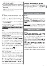
To perform the automation operation and programming tests, insert the
power
plug of the control unit
(supplied) in a mains socket (
fig. 41
) . If the socket is
far from the automation, use a suitable extension lead .
POWER SUPPLY CONNECTION
STEP 8
CAUTION!
The following operations described in this manual will be
performed on live electrical circuits and therefore manoeuvres may be
hazardous! Therefore proceed with care.
After powering up the control unit (
fig. 41
) perform the following operations,
checking conformity of results:
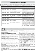
• Immediately after start-up, the
red
led (
fig. 42
) flashes quickly for a few sec-
onds, after which the
red
and
green
leds light up alternately; then the
green
led turns off and the
red
led continues flashing at regular intervals every second
(=
control unit operating status OK
)
.
CAUTION! - If the red led does not flash as described above, discon-
nect the Control unit from the power supply and carefully check all
connections (refer also to the paragraph “
What to do if....
”).
• If the system is equipped with photocells, check the RX element to ensure
that the led is
OFF
(=
operation OK
) or
ON
(=
obstacle present
) . If the Led is
flashing, this means that the signal is poor and subject to incorrect photocell
alignment .
• If the system is equipped with a radio control keypad, check operation with
reference to the relative instruction manual .
INITIAL START-UP AND ELECTRICAL
CONNECTION CHECK
English – 5
EN
Summary of Contents for SHEL60KIT
Page 2: ......
Page 81: ...IX 6 7 8 a b c d l e f h m g g 9...
Page 83: ...XI 15 a 15 b 17 M8 R8 x 24 V8 x 45 16 18 21 20 M6 V6 x 18 19...
Page 84: ...XII 22 V6 x 14 M6 B 0 400 mm 23 90 23 a 24 26 25 27...
Page 87: ...XV 45 46 43 T1 T3 T2 T4 44 A B...
Page 88: ...www niceforyou com Nice SpA Oderzo TV Italia info niceforyou com IS0438A00MM_18 04 2016...


