


ENGLISH –
9
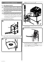
14.
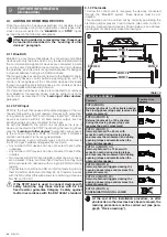
fasten the bracket to the gate leaf in the horizontal posi-
tion, using adequate screws (not supplied)
18
15.
fasten the arm to the bracket again using the pin and re-
taining ring just removed
16.
before locking the gearmotor, adjust the limit switches
Adjusting the mechanical limit switch-
“).
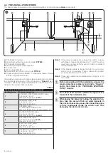
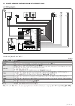
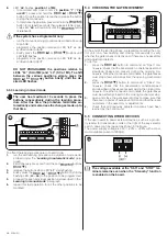
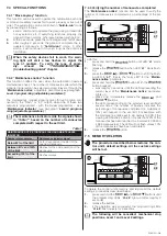
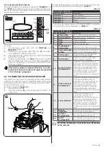
3.6 ADJUSTING THE MECHANICAL LIMIT
SWITCHES
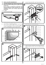
To adjust the limit switches, proceed as follows:
1.
unlock the gearmotor with the relevant key provided (refer
Manually unlocking and locking the gearmotor
”
paragraph)
2.
manually move the gate leaves to the fully open position
3.
position the limit switch (
A
) as shown in the figure
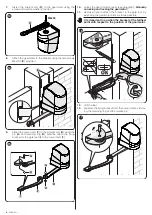
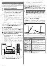
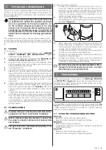
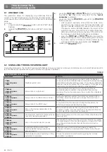
4.
loosen the screw that fastens the straight arm to the gear-
motor
5.
apply the protective cover (
B
) and re-tighten the screw
with the washer
A
B
19
6.
move the gate to the halfway open position and manually
lock the gearmotor.
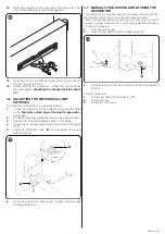
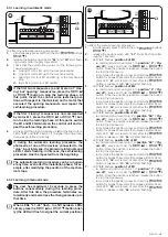
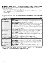
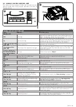
3.7 MANUALLY UNLOCKING AND LOCKING THE
GEARMOTOR
The gearmotor is equipped with a mechanical unlocking device
that can be used to open and close the gate manually.
These manual operations should only be performed in case of
a power outage, malfunctions or during the installation phases.
To unlock the device:
1.
raise the small cover
2.
insert the key (
A
) and turn it clockwise by 90°
A
20
3.
the gate leaf can now be moved manually to the desired
position.
To lock the device:
1.
turn the key (
A
) anti-clockwise by 90°
2.
remove the key
3.
lower the small cover.