
6
– ENGLISH
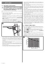
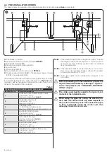
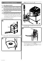
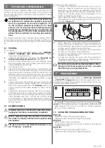
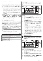
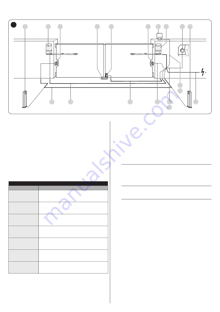
3.4 PRE-INSTALLATION WORKS
The figure shows an example of an automation system, constructed using
Nice
components.
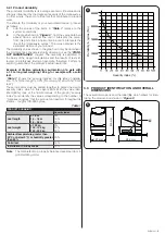
A
B
4
2
3
1
4
5
4
6
7
E
D
G
H A
C
C
F
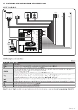
6
A
Photocells on column
B
Gearmotor without control unit (model
PP7224
)
C
Photocells (model EPM)
D
Mechanical stop at closed position
E
Electric lock
F
Warning light MLBT
G
Gearmotor with control unit (model
PP7124
)
H
Digital keypad (model EDSB) - Transponder reader (model
ETPB) - Key selector EKSU)
These above-mentioned components are positioned according
to a typical standard layout. Using the layout in “
Figure
” as a
reference, define the approximate position in which each com-
ponent of the system will be installed.
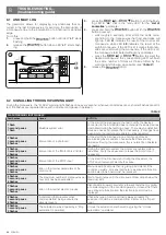
Table 2
TECHNICAL SPECIFICATIONS OF ELECTRICAL CABLES
Identification no.
Cable characteristics
1
CONTROL UNIT POWER SUPPLY cable
1 cable 3 x 1.5 mm
2
Maximum length 30 m [
note 1
]
2
WARNING LIGHT cable
1 cable 2 x 1 mm
2
Maximum length 20 m
3
ANTENNA cable
1 x RG58-type shielded cable
Maximum length 20 m; recommended < 5 m
4
BLUEBUS DEVICES cable
1 cable 2 x 0.5 mm
2
Maximum length 20 m [
note 2
]
5
KEY SELECTOR cable
2 cables 2 x 0.5 mm
2
[
note 3
]
Maximum length 50 m
6
ELECTRIC LOCK cable
1 cable 2 x 1 mm
2
Maximum length 6 m
7
GEARMOTOR POWER SUPPLY cable
1 cable 3 x 1.5 mm
2
Maximum length 10 m
Note 1
If the power supply cable is longer than 30 m, a cable
with larger cross-sectional area (3 x 2.5 mm
2
) must be
used and a safety earthing system must be installed
near the automation.
Note 2
If the BlueBus cable is longer then 20 m, up to maxi-
mum 40 m, it is necessary to use a cable with a greater
cross-sectional area (2 x 1 mm
2
).
Note 3
These two cables can be replaced by a single 4 x 0.5
mm
2
cable.
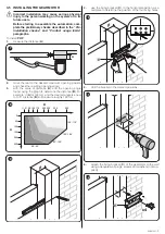
a
Before proceeding with the installation, prepare the
required electrical cables by referring to “Figure 6”
and to that stated in the “TECHNICAL SPECIFICA-
a
The cables used must be suited to the type of envi-
ronment of the installation site.
a
When laying the pipes for routing the electrical ca-
bles, take into account that any water deposits in
the junction boxes may cause the connection pipes
to form condensate inside the control unit, thus
damaging the electronic circuits.