


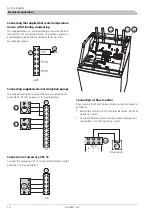


Connecting the supplied hot water temperature
sensor with floating condensing
The supplied sensor is connected using a two-wire cable to
terminal X21 (21) positions 5 and 6. The sensor is placed in
a submerged tube on the accumulator tank, e.g. VPA.
See docking options.
-X21
Connecting supplied external circulation pumps
The supplied circulation pumps (156) are connected to ter-
minal block -X7 (22) positions 1 to 6 as illustrated.
22
156
156
-X7
Connection of accessory VST 12
Connect the accessory VST 12 to the terminal block -X6 (6)
positions 2 to 5 as illustrated.
6
-X6
F1127 mitsubishi AK 8kW
F1125 mitsubishi (gammalt)
95
68
6
22
9
21
30
29
20
26
13
97
2
164
95
68
6
22
9
21
30
29
26
13
97
14
2
22
21
30
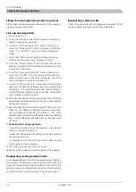
Connection of flow monitor
Flow monitor (154) with normal closing contact connected
as follows:
■
Disconnect U-link no. 875 from terminal block -X30 (30)
positions 1 and 2.
■
Connect a floating normal closing contact between ter-
minal block -X30 (30) positions 1 and 2.
SELV
+
B
A
ñ
B
+
ñ
A
RTG
EXT, EL
UG
1
2
3
4
5
6
7
8
30
86
15
4
1
2
6
SELV
+
B
A
ñ
B
+
ñ
A
RTG
EXT, EL
UG
1
2
3
4
5
6
7
8
30
154
Flödesvakt
Flow sensor
FIGHTER 1127
18
For the Installer
Electrical connections
Summary of Contents for FIGHTER 1127
Page 2: ...LEK LEK LEK LEK LEK LEK LEK LEK LEK LEK...
Page 26: ...Electrical circuit diagram FIGHTER 1127 24 Miscellaneous Technical specifications...
Page 27: ...25 FIGHTER 1127 Miscellaneous Technical specifications...
Page 28: ...FIGHTER 1127 26 Miscellaneous Technical specifications...
Page 29: ...27 FIGHTER 1127 Miscellaneous Technical specifications...
Page 35: ......


