


13
XWW-stop 65 °C
XWW-int 14d
XWW-stop
[P]
Extra hot water stop temperature.
Basic setting: 65.
Setting range: 60 – 65.
XWW-int
[P]
Interval in days for periodic extra hot water.
Basic setting: 14.
Setting range: 1 – 90.
14
HP/MS 1 LP1
HP/MS:
Shows status of high-pressure pressure
switches/motor protection (
1
= closed,
0
= open). Gives a
permanent alarm. Manual resetting of the motor protection.
LP:
Shows the status of the low-pressure pressure switch (
1
= closed,
0
= open). Gives a permanent alarm.
15
Brine pump 0
EP-drift 0
Brine pump:
Forced operation of brine pump. Change
0
to
1
using the ”Increase” button and press the ”Operating
mode” button.
1
is then replaced with ”
Brine
”. Return to
normal mode after 10 days or with a restart.
EP-drift:
If a change to electric boiler mode (e.g. before the
collector installation is complete)is required, change
0
to
1
and press the ”Operating mode” button. The figure is then
supplemented with ”
EP
”.
Selectable operating modes:
Compressor operation.
0
1-step EP-drift (after acknowledgement).
1
16
Cal.Out 0 Room 0
Brine In 0 Brine O 0
Cal. Out
[P]
Calibration of outside sensors.
Room
[P]
Calibration of room sensor.
Brine In
[P]
of brine flow sensor.
Brine O
[P]
Calibration of brine return.
Setting values for all quantities: -5 – +5.
17
Man 0
Man:
Manual test of outputs. Change ”
Man 0
” to ”
Man
1
” or ”
Man 2
” to test different functions. To exit the menu
”
Man 0
” must be set.
Start contactor, HP
Relay K1:
Operating contactor, HP
Relay K2:
Brine pump
Relay HTF:
Shuttle valve
Relay VX:
Circulation pump
Relay HC:
Not active
Relay L:
Pump, cooling
Relay PK:
Pump, dump
Relay PD:
Addition
Relay T3:
Example:
Man2 VB 0 L 0
PK 0 PD 0 T3 0
18
Service time 0
Parallel
Service time:
Change from 0 to 1 to speed up the period
of time by 60 times. Resets 8 minutes after the last button
was pushed.
Parallel:
Current setting for the rotary potentiometer ”In-
crease/Reduce” heating to offset the heating curve (parallel
offset).
FIGHTER 1127
12
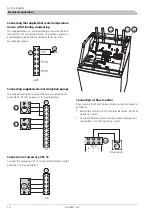
For the Installer
Control (also with accessories)
Summary of Contents for FIGHTER 1127
Page 2: ...LEK LEK LEK LEK LEK LEK LEK LEK LEK LEK...
Page 26: ...Electrical circuit diagram FIGHTER 1127 24 Miscellaneous Technical specifications...
Page 27: ...25 FIGHTER 1127 Miscellaneous Technical specifications...
Page 28: ...FIGHTER 1127 26 Miscellaneous Technical specifications...
Page 29: ...27 FIGHTER 1127 Miscellaneous Technical specifications...
Page 35: ......


