


Preparations
TIP
If the ventilation is to be adjusted before heat
pump operation starts, the cooling modules
have to be deactivated in menu 5.2.3.
Pipe
After pipe installation, but before insulating, the system’s
brine side has to be filled with water, vented and pres-
sure-tested. After this, the pipes have to be flushed and
vented. Finally, the system has to be filled with a 28%
mixture of ethylene glycol and water.
The heating medium side should also be flushed and
pressure tested with water.
NOTE
Pay attention to nearby electricity sources
when you are working with liquids.
NOTE
Always wear protective gloves before starting
work.
NOTE
Take care not to damage the environment in
the work area. Risk of flooding.
NOTE
Check that the components necessary for unit
operation are installed and connected to
GreenMaster-HP.
1. Ensure that GreenMaster-HP has not been damaged
during transport.
2. Check that the switch (SF1) is in position " ".
3. Check for water in any hot water heater and climate
system.
4. Follow the start guide, see page 37, when the system
is ready for start-up.
Caution
Check the miniature circuit-breaker and the
motor protection breakers. They may have
tripped during transportation.
NOTE
Do not start GreenMaster-HP if there is a risk
that the water in the system has frozen.
Ventilation
Check that:
1. The fan (GQ2) can rotate freely and there are no
loose parts remaining in the fan chamber.
2. Connector (HR10) next to the fan is in position AUTO.
3. Air filters (HQ10) are clean and intact.
4. The heat exchanger’s (EP10) fins and pipes are clean
and intact.
5. The air ducts are correctly connected to GreenMas-
ter-HP.
6. Sensor (BP12) is connected correctly.
7. Any external accessories are correctly connected.
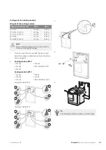
Flushing
Before starting
Make sure that:
1. All shut-off valves are open.
2. All drain, service, vent and filling valves are closed.
3. No other connections in the pipe system are open.
4. Filler connection (XL27) is connected to the prop-
erty’s water supply.
5. Filler connection (XL28) is connected to the drain
with a flexible hose.
6. Pressure gauge (BP6) is not damaged. In the event
of a pressure increase above 3 bar, there is a risk of
safety valves being tripped.
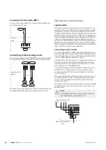
Brine system
XL27
QM34
CM2
QM2.2
QM2.1
CM3
BP6
XL28
XL27
XL28
QM34
GreenMaster-HP
Chapter 6 |
Commissioning and adjusting
32
6 Commissioning and adjusting