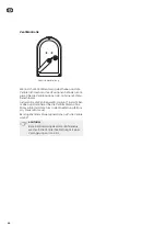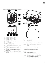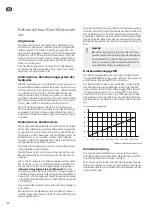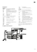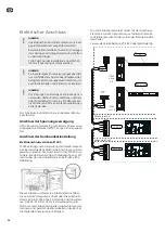
Electrical connection
NOTE
All electrical connections must be carried out
by an authorised electrician.
Electrical installation and wiring must be car-
ried out in accordance with the stipulations in
force.
F1345 must not be powered when installing
HPAC 45.
NOTE
If the supply cable is damaged, only NIBE, its
service representative or similar authorised
person may replace it to prevent any danger
and damage.
NOTE
To prevent interference in the event of any
splicing, communication and/or sensor cables
to external connections must not be laid closer
than 20 cm from high voltage cables.
The electrical circuit diagram is at the end of these in-
stallation instructions.
Connecting the supply
HPAC 45 is factory fitted with power cable and plug
(W101, length 3,0 metres).
Connecting communication
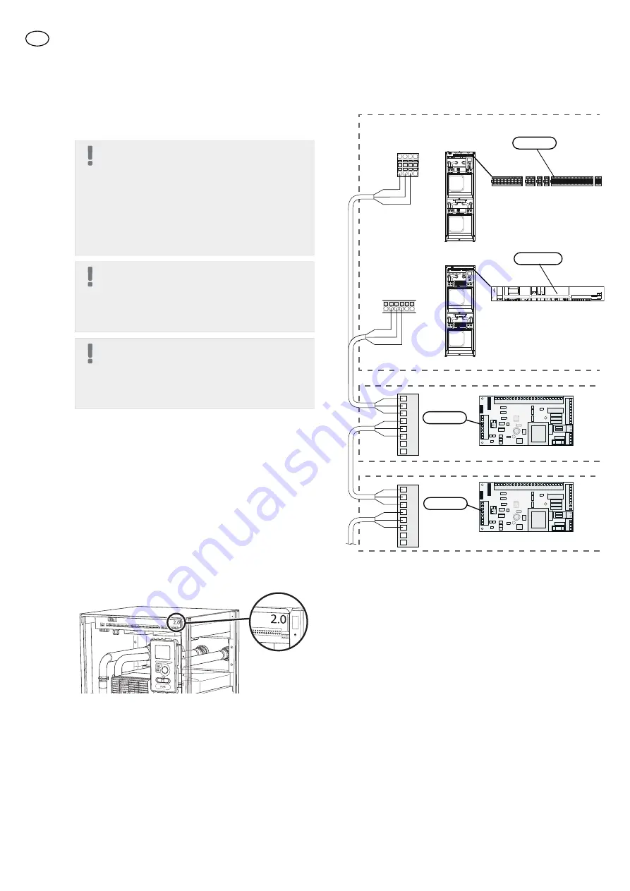
Electrical connection versions F1345
F1345 has different electrical connection versions de-
pending on when the heat pump was manufactured.
To check which electrical connection applies to your
F1345, check the designation "2.0" visible above the
right hand side of the terminal block as illustrated.
L
EK
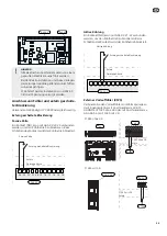
This accessory contains an accessory board (AA5) that
must be connected directly to the heat pump on the
input board (terminal block X6 in F1345 without 2,0
or on terminal block -AA101 -X10 in F1345 with 2,0.
If several accessories are to be connected or are already
installed, the following instructions must be followed.
The first accessory board must be connected directly
to the terminal block in the heat pump and the follow-
ing boards must be connected in series with the previ-
ous board.
Use cable type LiYY, EKKX or similar.
1
2
3
4
5
6
7
8
AA5-X4
A
B
GND
A
B
GND
A
B
GND
A
B
GND
1
2
3
4
5
6
7
8
AA5-X4
X6
1
2
3
4
A
B
GND
1
2
3
4
5
6
7
8
1
2
3
4
5
6
7
8
LEK
LEK
L1
-X3
-X4
1 2
3
-AA101
-AA101
N
L2 L3
1 2
3
4
5
6
7
8
9
-X5
1 2
3
4
5
6
7
8
9
-X6
-X7
-X8
-X9
-FC1
-AA101
-AA101
-AA101
-AA101
-AA101
1 2
3
4
1 2
3
1 2
3
1 2
3
4
5
-X10
A B
A B
-AA3-X7
K1
-AA101
K2 K3
C
C NO NC
K4
C NO NC
QN10
GP16
L N
L
L
L N N N
L
N
L N PE
PE
6
7
8
9 10 11 12 13 14 15 16 17 18 19 20 21 22
12
V A B
13 14
-BE1
-GP16
-BE2
-BE3
AUX 4
AUX 5
1 2
3
4
5
6
7
8
9 10 11 12 13 14 15
-AA3
-X6
0-10V
-EP14 -EP15
-BF1
16 17 18
2
-AA3
-X22
-AA3
-AA3
-X20
-X21
1 3
1 2 3
-X23
-BT1
-BT50
-BT25
-BT6
AUX 1
AUX 2
AUX 3
-BT7
-BT71
2.0
3
4
5
-X10
-AA101
6
7
A
B
GND
X6
AA101:X10
F1345
without
2.0
F1345
with
2.0
Accessory card
1
Accessory card
2
ON
1
2
3
4
5
6
7
8
-X9
-X2
24
20
21
22
23
15
16
17
18
19
10
11
12
13
14
5
6
7
8
9
1
1
N
L
PE
PE
1
2
3
4
5
6
7
8
2
3
4
5
6
7
8
9
2
3
4
-X8
-X4
-X10
-X1
ON
1
2
3
4
5
6
7
8
-X9
-X2
24
20
21
22
23
15
16
17
18
19
10
11
12
13
14
5
6
7
8
9
1
1
N
L
PE
PE
1
2
3
4
5
6
7
8
2
3
4
5
6
7
8
9
2
3
4
-X8
-X4
-X10
-X1
AA5-X4
AA5-X4
22
GB
Summary of Contents for 067446
Page 2: ......
Page 13: ...Tekniska uppgifter Mått 235 160 75 495 235 100 600 450 75 685 135 920 150 75 150 150 13 SE ...
Page 25: ...Technical data Dimensions 235 160 75 495 235 100 600 450 75 685 135 920 150 75 150 150 25 GB ...
Page 37: ...Technische Daten Maße 235 160 75 495 235 100 600 450 75 685 135 920 150 75 150 150 37 DE ...
Page 51: ...51 Elschema Electrical wiring diagram Elektrischer schaltplan Esquema del circuito eléctrico ...
Page 52: ......
Page 53: ......
Page 54: ......
Page 55: ......
Page 56: ...NIBE AB Sweden Hannabadsvägen 5 Box 14 SE 285 21 Markaryd info nibe se www nibe eu 331482 ...


