


16. Configure the power sensor to correct for the
Test Point Frequency
value using the power
sensor frequency correction function.
17. Use the power sensor to measure the power in dBm.
18. Repeat steps 15 through 17 for each configuration in the
Power Splitter Characterization
table, recording each result as
splitter output 1 power
, where each configuration has a
corresponding value.
19. Calculate the splitter imbalance for each frequency point using the following equation:
splitter imbalance
=
splitter output 2 power
-
splitter output 1 power
20. Disconnect the 50 Ω SMA terminator (f) from splitter output 2. Refer to the remaining
assembly as the
power sensor assembly
. The power sensor assembly will be used in the
Verifying Flatness and Bandwidth
procedure.
Related Information
Verifying Flatness and Bandwidth
on page 18
Follow this procedure to verify the analog flatness and bandwidth accuracy of the
NI 5170R by generating a sine wave and comparing the amplitude measured by the
NI 5170R to the amplitude measured by the power sensor.
Verification
This section provides instructions for verifying the device specifications.
Verification of the NI 5170R is complete only after you have successfully completed all tests
in this section using the
As-Found Limits
.
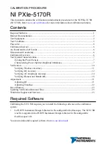
Refer to the following figure for the names and locations of the NI 5170R front panel
connectors. You can find information about the functions of these connectors in the device
getting started guide.
10
|
ni.com
|
NI PXIe-5170R Calibration Procedure


