NI PCI-5122 Getting Started Manual Download Page 5

If the installation window does not appear, navigate to the drive, double-click it, and
double-click 

autorun.exe

.

3.

Follow the instructions in the installation prompts.

Note


Windows users may see access and security messages during

installation. Accept the prompts to complete the installation.

4.

When the installer completes, select 

Restart

 in the dialog box that prompts you to restart,

shut down, or restart later.

Installing the PXI/PXIe-5122

Caution


To prevent damage to the PXI/PXIe/PCI-5122 caused by ESD or

contamination, handle the module using the edges or the metal bracket.

1.

Ensure the AC power source is connected to the chassis before installing the module.

The AC power cord grounds the chassis and protects it from electrical damage while you
install the module.

2.

Power off the chassis.

3.

Inspect the slot pins on the chassis backplane for any bends or damage prior to
installation. Do not install a module if the backplane is damaged.

4.

Remove the black plastic covers from all the captive screws on the module front panel.

5.

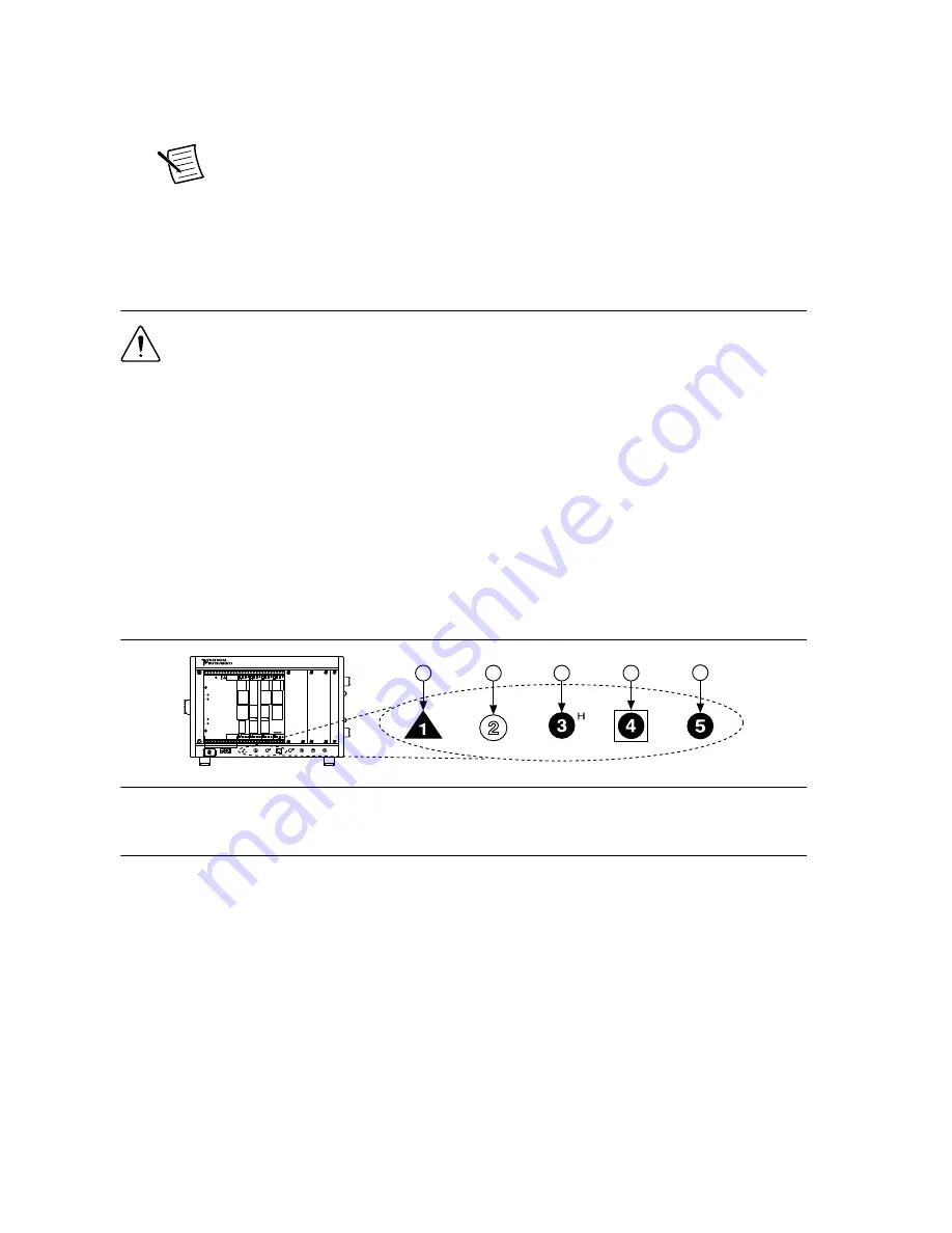
Identify a supported slot in the chassis. The following figure shows the symbols that
indicate the slot types.

Figure 1. Chassis Compatibility Symbols

NI PXIe-1062Q

1

2

3

4

5

1. PXI Express System Controller Slot
2. PXI Peripheral Slot
3. PXI Express Hybrid Peripheral Slot

4. PXI Express System Timing Slot
5. PXI Express Peripheral Slot

PXI modules can be placed in PXI peripheral slots or PXI Express Hybrid peripheral
slots. PXI Express modules can be placed in PXI Express peripheral slots, PXI Express
Hybrid peripheral slots, or PXI Express System Timing slots.

6.

Touch any metal part of the chassis to discharge static electricity.

7.

Ensure that the ejector handle is in the downward (unlatched) position.

8.

Place the module edges into the module guides at the top and bottom of the chassis. Slide
the module into the slot until it is fully inserted.

NI PXI/PXIe/PCI-5122 Getting Started Guide

  | 

© National Instruments

  | 

5

Summary of Contents for PCI-5122

Page 1: ...netic Compatibility Guidelines 2 Verifying the System Requirements 2 Unpacking the Kit 2 Kit Contents 3 Preparing the Environment 3 PXI Modules 3 PXI Express Modules 4 PCI Modules 4 Installing the Software 4 Installing the PXI PXIe 5122 5 Installing the PCI 5122 6 Front Panel Connectors and Indicators 8 Configuring the PXI PXIe PCI 5122 in MAX 9 Programming the PXI PXIe PCI 5122 10 NI SCOPE Exampl...

Page 2: ...urthermore any changes or modifications to the product not expressly approved by National Instruments could void your authority to operate it under your local regulatory rules Verifying the System Requirements To use the PXI PXIe PCI 5122 your system must meet certain requirements For more information about minimum system requirements recommended system and supported application development enviro...

Page 3: ...ng the PXI PXIe PCI 5122 meets the following specifications PXI Modules Operating Environment Ambient temperature range 0 C to 55 C Tested in accordance with IEC 60068 2 1 and IEC 60068 2 2 Relative humidity range 10 to 90 noncondensing Tested in accordance with IEC 60068 2 56 Maximum altitude 2 000 m at 25 C ambient temperature Pollution Degree 2 Indoor use only NI PXI PXIe PCI 5122 Getting Start...

Page 4: ...nd IEC 60068 2 2 Relative humidity range 10 to 90 noncondensing Tested in accordance with IEC 60068 2 56 Maximum altitude 2 000 m at 25 C ambient temperature Pollution Degree 2 Indoor use only Caution Clean the hardware with a soft nonmetallic brush Make sure that the hardware is completely dry and free from contaminants before returning it to service For complete specifications refer to specifica...

Page 5: ...or to installation Do not install a module if the backplane is damaged 4 Remove the black plastic covers from all the captive screws on the module front panel 5 Identify a supported slot in the chassis The following figure shows the symbols that indicate the slot types Figure 1 Chassis Compatibility Symbols NI PXIe 1062Q 1 2 3 4 5 1 PXI Express System Controller Slot 2 PXI Peripheral Slot 3 PXI Ex...

Page 6: ...ze cooling air flow depending on your application 12 Power on the chassis Note For more information about maximizing cooling air flow refer to the Maintain Forced Air Cooling Note to Users included in your kit Related Information Why Is the ACCESS LED Off When the Chassis Is On on page 12 Installing the PCI 5122 1 Power off and unplug the computer 2 Access the computer system expansion slots This ...

Page 7: ...facturers use a securing lever made of plastic to secure PCI devices such a lever is unacceptable and must be removed Use the screw provided in the kit to screw down the device Otherwise you must use a different computer chassis 8 Replace any access panels on the computer case 9 Power on your computer 10 Verify that spread spectrum clocking is enabled in the PC BIOS For information about how to ve...

Page 8: ...tors Label Function Connector Type CH 0 Analog input BNC female CH 1 Analog input BNC female TRIG External analog trigger BNC female CLK IN Sample clock input and Reference clock input SMB jack CLK OUT Sample clock output and Reference clock output SMB jack AUX I O PFI 0 and PFI 1 lines for digital trigger input output and probe compensation PFI 1 only 9 pin mini circular DIN 8 ni com NI PXI PXIe ...

Page 9: ...X is automatically installed with NI SCOPE 1 Launch MAX 2 In the configuration tree expand Devices and Interfaces to see the list of installed devices Installed devices appear under the name of their associated chassis 3 Expand your Chassis tree item MAX lists all devices installed in the chassis Your default device names may vary Note If you do not see your device listed press F5 to refresh the l...

Page 10: ...rol waveforms directly from your computer You can also run multiple sessions of the NI SCOPE SFP simultaneously NI SCOPE Instrument Driver LabVIEW Available on the LabVIEW Functions palette at Measurement I O NI SCOPE The NI SCOPE API configures and operates the device hardware and provides customizable acquisition control analysis and measurement options using LabVIEW VIs or LabWindows CVI functi...

Page 11: ...sic Locate examples in the file directory Users Public Public Documents National Instruments NI SCOPE examples Making a Measurement You can make a measurement interactively using the NI SCOPE SFP or programmatically using LabVIEW Making a Measurement with NI SCOPE SFP 1 Connect CH 0 to an input signal 2 Launch the NI SCOPE SFP from the Start menu 3 In the Select Device dialog box select the device...

Page 12: ...ble between the PCI devices to physically share triggers and or clocks 2 Launch MAX 3 In the MAX configuration pane right click Devices and Interfaces and select Create New 4 In the dialog box that opens select NI RTSI Cable 5 Click Finish 6 In the MAX configuration pane right click the NI RTSI cable select Add Device to NI RTSI Cable and select the device you want to add For more information abou...

Page 13: ...PXI PXIe PCI 5122 Doesn t Appear in MAX 1 In the MAX configuration tree expand Devices and Interfaces 2 Expand the Chassis tree to see the list of installed hardware and press F5 to refresh the list 3 If the module is still not listed power off the system ensure that all hardware is correctly installed and restart the system 4 Navigate to the Device Manager Operating System Description Windows 10 ...

Page 14: ...2 Reinstall the device and make any necessary adjustments to make sure that the device is effectively cooled 3 Power on the computer or chassis Note The thermal shutdown error is reported until the device has cooled to an acceptable operating temperature and has been successfully reset For more information about cooling the device refer to the Maintain Forced Air Cooling Note to Users included in ...

Page 15: ... MHz Oscilloscope NI PXIe 5160 Worldwide Support and Services The NI website is your complete resource for technical support At ni com support you have access to everything from troubleshooting and application development self help resources to email and phone assistance from NI Application Engineers Visit ni com services for NI Factory Installation Services repairs extended warranty and other ser...

Page 16: ...erein are trademarks or trade names of their respective companies For patents covering NI products technology refer to the appropriate location Help Patents in your software the patents txt file on your media or the National Instruments Patent Notice at ni com patents You can find information about end user license agreements EULAs and third party legal notices in the readme file for your NI produ...

Reviews: