


Hardware Front Panel Connectors
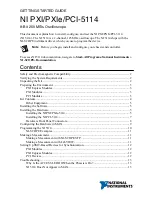
Refer to the following figure and table for the NI 5114 front panels and signal connectors.
Figure 5.
NI 5114 Front Panels
TRIG
CH 0
CH 1
AUX I/O
+5 V
MAX
CLK IN
TRIG
CH 0
125MHz Oscilloscope
ACCESS
ACTIVE
CH 1
AUX
I/O
+5 V
MAX
CLK IN
TRIG
CH 0
ACCESS
ACTIVE
CH 1
AUX
I/O
+5 V
MAX
CLK IN
125MHz Oscilloscope
Table 1.
NI 5114 Front Panel Signal Connections
Connector
Description
Function
CH 0, CH 1 BNC female
Analog input connection; digitizes data and triggers
acquisitions.
TRIG
BNC female
External analog trigger connection; signals on the
TRIG connector cannot be digitized.
8
|
ni.com
|
NI PXI/PXIe/PCI-5114 Getting Started Guide


