


www.nexusrobot.com Robot Kits manual
21
¾
Motor Control
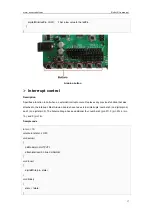
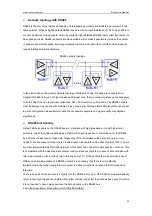
Hardware Setting
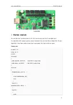
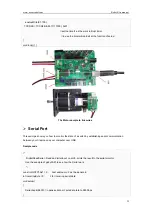
Connect four motor wires to Motor Terminal. And apply power through motor power terminal.
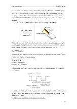
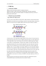
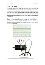
The PWM DC motor control is implemented by manipulating two digital IO pins and two PWM pins. As
illustrated in the diagram above, Pin 4,7 are motor direction control pins, Pin 5,6 are motor speed control
pins.
Pin Allocation
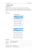
PWM Control Mode
"PLL Mode"
Pin
Function
Digital 4
Motor 1 Enable control
Digital 5
Motor 1 Direction control
Digital 6
Motor 2 Direction control
Digital 7
Motor 2 Enable control
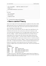
Sample code
int E1= 6; //the pin to control mator’s speed
int M1= 7; //the pin to control direction
void setup()
{
pinMode(M1,OUTPUT); //M2 direction control
pinMode(E1,OUTPUT); //E2 PWM speed control
"PWM Mode"
Pin
Function
Digital 4 Motor 1 Direction control
Digital 5 Motor 1 PWM control
Digital 6 Motor 2 PWM control
Digital 7 Motor 2 Direction control
Summary of Contents for Nexus Robot
Page 74: ...www nexusrobot com Robot Kits manual 70 Sample Wiring Diagram for RB004 2WD V2 0...
Page 92: ...www nexusrobot com Robot Kits manual 88 Diagram for Omni3WD_V1 0...
Page 96: ...www nexusrobot com Robot Kits manual 92 Diagram_Omni3WD_V3 3...
Page 118: ...www nexusrobot com Robot Kits manual 114 Sample Wiring Diagram for RB011 Mecanum 4WD V4 1...