


June 2020
Shark SD110/SD120 | 11
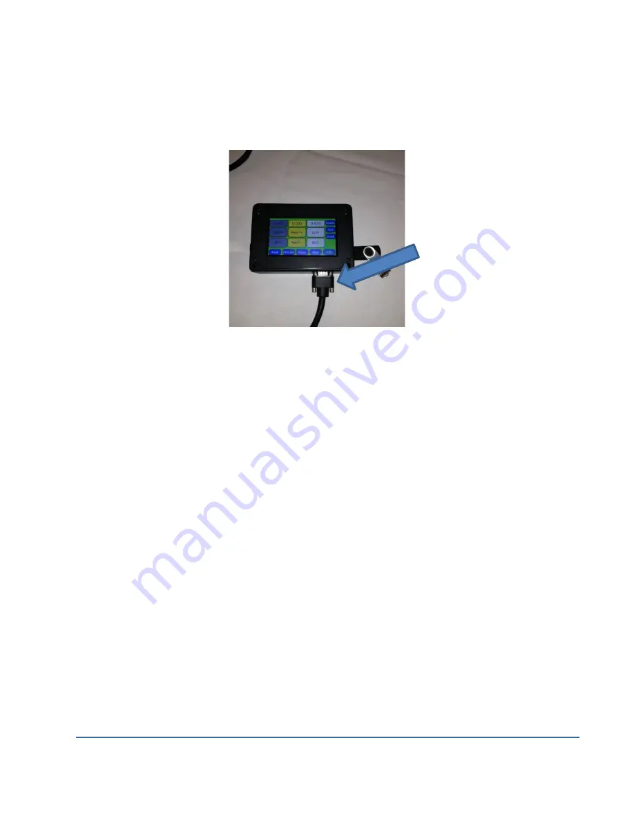
Place the Controller Interface in a comfortable easy to access location and connect it to the
Shark SD110/SD120 using the serial cable provided. The LCD Pendant gets its power from the
Controller Interface so no other power cords are needed. See image below.
Shark SD110/SD120 Cable Connections
Applying power to the Controller Interface.
•
Re-verify that all three axis drive cables are connected to their respective Controller
Interface leads. (should be labeled)
•
You should arrange the drive motor cables, power cables, and USB cable in a manner
that minimizes overlap, even amongst cables of the same purpose. This will reduce any
opportunity for signal interference because of
cables ‘laying on top of each other’.
•
Plug the Shark SD110/SD120 Power Supply into a 120V AC wall outlet, power strip, or
surge protector. Once again, we recommend that a power strip with an on/off switch is
used.
•
You will also hear a slight bumping or clicking noise coming from each of the motors
when power is initially supplied. This noise is momentary, and will occur every time
power is applied to the Controller Interface.
The Shark SD110/SD120
machine’
s hardware is now completely setup and is ready for basic
operation testing. You must register and setup the Shark SD110/SD120 software before you
can completely test your Shark SD110/SD120 machine.


