background image

Copyright © 2015 NEXCOM International Co., Ltd. All Rights Reserved.

55

OPPC 1540HT-J1900/1940HT-J1900 User Manual 

Chapter 3: System Setup

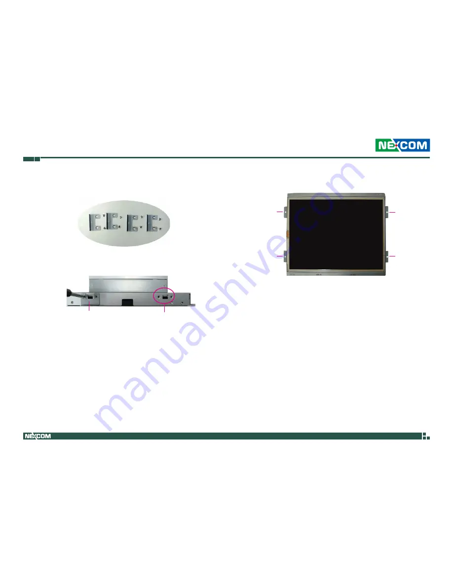
3.  Mount the brackets to their corresponding mounting holes located on 

the sides of the Panel PC.

Brackets and their corresponding 

mounting screws

Mounting 

holes

Bracket

4.  The photo below shows the 4 brackets mounted in place.

Bracket

Bracket

Bracket

Bracket

Summary of Contents for OPPC 1540HT-J1900

Page 1: ...NEXCOM International Co Ltd NEXCOM International Co Ltd Published August 2017 www nexcom com IoT Automation Solutions Business Group Open Frame Panel PC OPPC 1540HT J1900 1940HT J1900 User Manual ...

Page 2: ...n OPPC 1540HT J1900 1 Specifications 2 OPPC 1940HT J1900 4 Specifications 5 Knowing Your OPPC Series 7 Rear Bottom 7 Rear 8 Mechanical Dimensions 9 OPPC 1540HT J1900 9 OPPC 1940HT J1900 10 Chapter 2 Jumpers and Connectors Before You Begin 11 Precautions 11 Jumper Settings 12 Locations of the Jumpers and Connectors 13 Top View 13 Bottom View 14 Jumpers and DIP Switch Settings 15 RTC and SRTC Clear ...

Page 3: ...ng Control Input Connector 33 LVDS MCU FW Debug Connector 33 Smart Fan Connector 34 Battery Connector 34 Post Code Debug Connector 35 SIM Card Slot 35 Mini PCIe Slot 36 Mini PCIe Slot Wi Fi 3G 37 Block Diagram 38 Chapter 3 System Setup Installing a SATA Hard Drive 39 Installing a CFast Card 43 Installing a SO DIMM Memory Module 45 Installing a SATA DOM 46 Installing a Mini PCIe Module 50 Installin...

Page 4: ... J1900 are trademarks of NEXCOM International Co Ltd All other product names mentioned herein are registered trademarks of their respective owners Regulatory Compliance Statements This section provides the FCC compliance statement for Class A devices and describes how to keep the system CE compliant Declaration of Conformity FCC This equipment has been tested and verified to comply with the limits...

Page 5: ...1 000ppm and Polybrominated diphenyl Ethers PBDE 0 1 or 1 000ppm In order to meet the RoHS compliant directives NEXCOM has established an engineering and manufacturing task force to implement the introduction of green products The task force will ensure that we follow the standard NEXCOM development procedure and that all the new RoHS components and new manufacturing processes maintain the highest...

Page 6: ... Any claimed defect products that have been repaired or modified by persons who have not been authorized by NEXCOM or products which have been subjected to misuse abuse accident improper installation or usage not in accordance with the product instruction NEXCOM assumes no liability as a consequence of such events under the term of this warranty One example is the replacement of Tablet s or Hand h...

Page 7: ... the CPU and DIMM If the key parts are included please be noted clearly within the return form NEXCOM takes no responsibility for the parts which are not listed in the return form 4 Customers hold the responsibility to ensure that the packing of defective products is durable enough to be resistant against further damage due to the transportation damage caused by transportation is treated as Out of...

Page 8: ... products that returned a Basic Labor Cost and Testing Fee as Table listed b Parts Fee NEXCOM will charge for main IC chipsets such as the N B S B Super IO LAN Sound Memory and so on c 3rd party Device Fee products replacement for CPU DIMM HDD Chassis and UPS 2 Out of Warranty product will have a three months warranty for the fixed issues If the product failed with different problem within 3 month...

Page 9: ... can damage the soft metal or plastic parts of the connectors Safety Information Before installing and using the device note the following precautions Read all instructions carefully Do not place the unit on an unstable surface cart or stand Follow all warnings and cautions in this manual When replacing parts ensure that your service technician uses parts specified by the manufacturer Avoid using ...

Page 10: ...ter than the voltage and current rating marked on the product 10 All cautions and warnings on the equipment should be noted 11 If the equipment is not used for a long time disconnect it from the power source to avoid damage by transient overvoltage 12 Never pour any liquid into an opening This may cause fire or electrical shock 13 Never open the equipment For safety reasons the equipment should be...

Page 11: ...perating system version application software etc A complete description of the problem The exact wordings of the error messages Warning 1 Handling the unit carry the unit with both hands and handle it with care 2 Maintenance to keep the unit clean use only approved cleaning products or clean with a dry cloth 3 CFast Turn off the unit s power before inserting or removing a CFast storage card Conven...

Page 12: ...fice 13F No 920 Chung Cheng Rd ZhongHe District New Taipei City 23586 Taiwan R O C Tel 886 2 8226 7796 Fax 886 2 8226 7792 Email sales nexcom com tw www nexcom com tw NEXCOM Intelligent Systems Taichung Office 16F No 250 Sec 2 Chongde Rd Beitun Dist Taichung City 406 R O C Tel 886 4 2249 1179 Fax 886 4 2249 1172 Email sales nexcom com tw www nexcom com tw Japan NEXCOM Japan 9F Tamachi Hara Bldg 4 ...

Page 13: ...excom eu www nexcomitalia it NEXCOM Shanghai Room 603 604 Huiyinmingzun Plaza Bldg 1 No 609 Yunlin East Rd Shanghai 200333 China Tel 86 21 5278 5868 Fax 86 21 3251 6358 Email sales nexcom cn www nexcom cn NEXCOM Surveillance Technology Corp Room202 Building B the GuangMing Industrial Zone Zhonghua Rd Minzhi Street Longhua District Shenzhen 518131 China Tel 86 755 8364 7768 Fax 86 755 8364 7738 Ema...

Page 14: ...ted in the table Item Description Qty 1 Driver CD 1 2 Flat Head for HDD Installation 4 3 Panel Mount Kit 8 OPPC 1940HT J1900 Item Description Qty 1 Driver CD 1 2 Flat Head for HDD Installation 4 3 Panel Mount Kit 10 OPPC 1540HT J1900 Note Package contents may vary depending on your country region some items may be optional Please contact your local distributor for more information Panel Mount Kit ...

Page 15: ...ame Panel PC series Barebone OPPC 1540HT J1900 P N 90IQ1540H00X0 15 XGA LED backlight touch Panel PC with Intel Celeron J1900 2 0GHz 1000 nits touch screen 4GB DDR3L with 2x RS232 422 485 OPPC 1940HT J1900 P N 90IQ1940H00X0 19 SXGA LED backlight touch Panel PC with Intel Celeron J1900 2 0GHz 1000 nits touch screen 4GB DDR3L with 2x RS232 422 485 12V 60W AC DC power adapter w o power cord P N 74000...

Page 16: ...eleron J1900 Quad core low power consumption 1000 nits High brightness Flush Panel by 5 wire Touch Screen PS2 KB MS Line out Dual GbE 3x USB 2x RS232 422 485 2nd display VGA 1x Mini PCIe socket 1x CFast Remote power switch DDR3L 4GB 2 5 HDD bracket Support JMobile HMI Citect SCADA and CODESYS SoftLogic optional Mounting support Panel Wall Stand VESA 100mm x 100mm Wide range power input 12V 30V DC ...

Page 17: ...ftware from 1 second to 255 seconds and from 1 minute to 255 minutes Tolerance 15 under room temperature 25 C H W status monitor monitoring system temperature and voltage Expansion 2x Mini PCIe sockets support optional Wi Fi 3 5G module Rear I O PS2 keyboard mouse Audio port 1x Line out Remote power switch Ethernet 2x RJ45 USB 2x USB 2 0 1x USB 3 0 COM 1 RS232 422 485 COM 2 RS232 422 485 Reset but...

Page 18: ...OPPC 1540HT J1900 1940HT J1900 User Manual Shock IEC 68 2 27 HDD 20G wall mount half sine 11ms Operating temperature 5 C to 50 C Storage temperature 20 C to 75 C Operating humidity 10 90 relative humidity non condensing Dimension 329 x 280 x 69 3mm Weight 4kg Certifications CE approval FCC Class A ...

Page 19: ...0 Quad core low power consumption 1000 nits High brightness Flush Panel by 5 wire Touch Screen PS2 KB MS Line out Dual GbE 3x USB 2x RS232 422 485 2nd display VGA 1x Mini PCIe sockets 1x CFast Remote power switch DDR3L 4GB 2 5 HDD bracket Support JMobile HMI Citect SCADA and CODESYS SoftLogic optional Mounting support Panel Wall Stand VESA 100mm x 100mm Wide range power input 12V 30V DC OPPC 1940H...

Page 20: ... by software from 1 second to 255 seconds and from 1 minute to 255 minutes Tolerance 15 under room temperature 25 C H W status monitor monitoring system temperature and voltage Expansion 1x Mini PCIe socket1 support optional Wi Fi 3 5G module Rear I O PS2 keyboard mouse Audio port 1x Line out Remote power switch Ethernet 2x RJ45 USB 2x USB 2 0 1x USB 3 0 COM 1 RS232 422 485 COM 2 RS232 422 485 Res...

Page 21: ...40HT J1900 1940HT J1900 User Manual Shock IEC 68 2 27 HDD 20G wall mount half sine 11ms Operating temperature 5 C to 50 C Storage temperature 20 C to 75 C Operating humidity 10 90 relative humidity non condensing Dimension 422 6 W x 350 6 H x 73 2 D mm Weight 6 15Kg Certifications CE approval FCC Class A ...

Page 22: ... Remote On Off Switch Used to connect a remote to power on off the system LAN 1 and LAN 2 Used to connect the system to a local area network LAN 1 supports Wake up on LAN USB 2 0 Dual USB 2 0 port for connecting USB 2 0 1 1 devices USB 3 0 Single USB 3 0 port for connecting the system with USB 3 0 2 0 devices COM 1 and COM 2 These COM ports support RS232 422 485 compatible series device through BI...

Page 23: ...User Manual Rear VESA Mounting Hole 100x100mm VESA Mounting Hole 100x100mm VESA Mounting Hole 75x75mm VESA Mounting Hole 75x75mm VESA Mounting Hole 100x100mm VESA Mounting Hole 100x100mm VESA Mounting Hole 75x75mm VESA Mounting Hole 75x75mm VESA Mounting Holes These are the mounting holes for VESA mounting 100x100mm and 75x75mm ...

Page 24: ...ser Manual Mechanical Dimensions 353 280 90 100 90 75 75 60 60 Ø4 50 12 304 10 LCD Active Area 228 10 LCD Active Area 24 45 25 95 10 170 10 90 120 90 174 30 12 256 40 85 12 27 50 16 150 53 75 100 75 100 8 M4 VESA HOLES 270 69 30 329 67 25 67 25 47 50 12 16 160 84 50 334 0 5 261 0 5 7 max CUT OUT SIZE T 7mm MAX OPPC 1540HT J1900 ...

Page 25: ...50x12L 80 30 55 70 55 80 30 422 60 0 3 350 60 0 3 376 32 Panel Active Area 301 06 Active Area 150 150 160 378 32 0 3 Viewing CUT OUT Size 303 06 0 3 Viewing CUT OUT Size 10 10 22 14 23 87 67 25 67 25 54 326 60 0 3 174 30 34 75 80 21 50 150 88 30 398 60 0 3 270 41 80 75 80 120 120 75 100 100 75 8 M4 VESA MOUNT 403 0 5 331 0 5 7 max CUT OUT SIZE T 7mm MAX OPPC 1940HT J1900 ...

Page 26: ...mponents make sure that the power is off Ground yourself before touching any internal components by touching a metal object Static electricity can damage many of the electronic components Humid environments tend to have less static electricity than dry environments A grounding strap is warranted whenever danger of static electricity exists Precautions Computer components and electronic circuit boa...

Page 27: ... setting the jumpers ensure that the jumper caps are placed on the correct pins When the jumper cap is placed on both pins the jumper is short If you remove the jumper cap or place the jumper cap on just one pin the jumper is open Refer to the illustrations below for examples of what the 2 pin and 3 pin jumpers look like when they are short on and open off Two Pin Jumpers Open Left and Short Right...

Page 28: ...1900 1940HT J1900 User Manual Chapter 2 Jumpers and Connectors Locations of the Jumpers and Connectors Top View JP7 JP5 J5 CN1 CN2 SW1 J7 J2 JP2 J6 J1 JP1 JP4 JP3 JP6 J4 J3 SW2 J10 J11 CN6 CN16 VGA1 CN12 CN10 CN5 USB1 LAN2 LAN1 JP10 CN3 JP14 JP12 CN7 CN8 CN9 CN11 J12 J13 CN4 J9 J8 ...

Page 29: ...Copyright 2015 NEXCOM International Co Ltd All Rights Reserved 14 OPPC 1540HT J1900 1940HT J1900 User Manual Chapter 2 Jumpers and Connectors SW3 J14 Bottom View ...

Page 30: ...lect Connector type 1x3 3 pin header 2 54mm pitch Connector location J12 RTC and J13 SRTC Pin Settings 1 2 On Normal 2 3 On Clear 1 2 On default Pin Definition 1 NC 2 RTC Power 3 GND 1 3 AT ATX Power Select Connector type 1x3 3 pin header 2 54mm pitch Connector location JP2 Pin Settings 1 2 On AT Mode 2 3 On ATX Mode 2 3 On default Pin Definition 1 AUTO AT MODE 2 PWRBT In 3 Manual ATX MODE 1 3 ...

Page 31: ... pitch Connector location JP6 Pin Settings Model 1 2 On 3 3V OPPC 1940HT J1900 2 3 On 5V OPPC 1540HT J1900 1 2 On default Pin Definition 1 VCC3 2 Power for Dimming 3 VCC5 1 3 LCD Panel VDD Power Select Connector type 1x3 3 pin header 2 54mm pitch Connector location JP3 Pin Settings Model 1 2 On 3 3V OPPC 1540HT J1900 2 3 On 5V OPPC 1940HT J1900 1 2 On default Pin Definition 1 VCC3 2 Power for VDD ...

Page 32: ...s Touch 4 5 Wire Select Connector type 1x3 3 pin header 2 54mm pitch Connector location JP4 1 3 Pin Settings 1 2 On 5 wire 2 3 On 4 wire 1 2 On default COM1 RI Pin Power Select Connector type 1x3 3 pin header 2 54mm pitch Connector location JP12 1 3 Pin Settings 1 2 On RING 2 3 On 5V 1 2 On default Pin Definition 1 SP1_RI 2 SP1_PSRI 3 VCC5 ...

Page 33: ...or type 1x3 3 pin header 2 54mm pitch Connector location JP14 1 3 Pin Settings 1 2 On RING 2 3 On 12V 1 2 On default Pin Definition 1 SP2_RI 2 SP2_PSRI 3 12V 1 O N 2 3 4 Panel Resolution Select Connector type 4 pin DIP switch Connector location SW2 Resolution SW2 1 SW2 2 SW2 3 SW2 4 Model 1024 x 768 ON OFF ON ON OPPC 1540HT J1900 1280 x 1024 OFF ON ON OFF OPPC 1940HT J1900 ...

Page 34: ...o Ltd All Rights Reserved 19 OPPC 1540HT J1900 1940HT J1900 User Manual Chapter 2 Jumpers and Connectors 1 O N 2 TYPE SW1 1 SW1 2 PWM Mode ON OFF Analog Mode OFF ON Dimming Type Select Connector type 2 pin DIP switch Connector location SW1 ...

Page 35: ...mpers and Connectors Connector Pin Definitions External I O Interfaces Line out Connector Connector type 1x 3 5mm TRS Connector location CN3 Pin Definition Pin Definition 1 LOUT_R 2 JD 3 NC 4 LOUT_L 5 GND 6 GND Pin Definition 1 PWRBT 2 GND 1 2 Remote Power On Off Switch Connector type 2 pin switch Connector location JP10 ...

Page 36: ... 1G network link Steady Orange 100Mbps network link Off 10Mbps or no link Pin Definition Pin Definition 1 LAN1M0P 2 LAN1M0N 3 LAN1M1P 4 LAN1M2P 5 LAN1M2N 6 LAN1M1N 7 LAN1M3P 8 LAN1M3N LAN2 Port Connector type RJ45 port with LEDs Connector location LAN2 ACT LINK 8 1 Act Status Flashing Yellow Data activity Off No activity Link Status Steady Green 1G network link Steady Orange 100Mbps network link O...

Page 37: ...onnector type USB 2 0 ports Type A Connector location USB1 Single USB 3 0 Port Connector type USB 3 0 port Type A Connector location CN5 Pin Definition Pin Definition 1 VCC5 2 USB 2N 3 USB 2P 4 GND 5 VCC5 6 USB 1N 7 USB 1P 8 GND Pin Definition Pin Definition 1 VCC5 2 USB 0N 3 USB 0P 4 GND 5 USB3_RX0_N 6 USB3_RX0_P 7 GND 8 USB3_TX0_N 9 USB3_TX0_P 1 5 4 8 4 5 1 9 ...

Page 38: ...XD Reserve 4 COM1_DTR COM1_RXD Reserve 5 COM1_GND COM1_GND Reserve 6 COM1_DSR COM1_RTS Reserve 7 COM1_RTS COM1_RTS Reserve 8 COM1_CTS COM1_CTS Reserve 9 COM1_RI Could be a 5V Power Pin COM1_CTS Could be a 5V Power Pin Reserve Could be a 5V Power Pin Pin RS232 RS422 RS485 1 COM2_DCD COM2_TXD COM2_TXD COM2_RXD 2 COM2_RXD COM2_TXD COM2_TXD COM2_RXD 3 COM2_TXD COM2_RXD Reserve 4 COM2_DTR COM2_RXD Rese...

Page 39: ...onnector type DB 15 port 15 pin D Sub Connector location VGA1 Pin Definition Pin Definition 1 Red 2 Green 3 Blue 4 N C 5 GND 6 GND 7 GND 8 GND 9 5V 10 GND 11 N C 12 DDC Data 13 HSYNC 14 VSYNC 15 DDC Clock 5 15 11 1 Pin Definition 1 DC 2 DC 3 GND G 3 1 12V 30V DC Power Input Connector type Phoenix Contact 1x3 3 pin terminal block Connector location CN16 ...

Page 40: ...dard CFast connector Connector location J14 Pin Definition Pin Definition S1 GND S2 SATA_TXP2 S3 SATA_TXN2 S4 GND S5 SATA_RXN2 S6 SATA_RXP2 S7 GND PC1 CFAST_CDI PC2 GND PC3 NC PC4 NC PC5 NC PC6 NC PC7 GND PC8 CFAST_LED1_C PC9 CFAST_LED2_C PC10 NC PC11 NC PC12 NC PC13 VCC3 PC14 VCC3 PC15 GND PC16 GND PC17 CFAST_CDO Pin Definition 1 Reset 2 Reset 3 GND 4 GND Reset Button Connector location SW3 ...

Page 41: ... 5mm pitch Connector location J4 Pin Definition Pin Definition 1 VCC5 2 12V 3 12V 4 BKCTRL 5 GND 6 GND 7 BKLEN 7 1 LVDS Channel A Connector type 2x10 20 pin header 1 25mm pitch Connector location CN2 Pin Definition Pin Definition 1 NC 2 NC 3 VDD 4 LVDS_DAT0P 5 LVDS_DAT3P 6 LVDS_DAT0N 7 LVDS_DAT3N 8 VDD 9 GND 10 LVDS_DAT1P 11 LVDS_CLK1P 12 LVDS_DAT1N 13 LVDS_CLK1N 14 GND 15 GND 16 12V 17 LVDS_DAT2P...

Page 42: ...inition Pin Definition 1 NC 2 NC 3 VDD 4 LVDS_DAT4P 5 LVDS_DAT7P 6 LVDS_DAT4N 7 LVDS_DAT7N 8 VDD 9 GND 10 LVDS_DAT5P 11 LVDS_CLK2P 12 LVDS_DAT5N 13 LVDS_CLK2N 14 GND 15 GND 16 12V 17 LVDS_DAT6P 18 12V 19 LVDS_DAT6N 1 19 2 20 Line in Mic in Connector Connector type 2x4 8 pin header 2 54mm pitch Connector location JP1 Pin Definition Pin Definition 1 LINE IN LP 2 MIC1_L3 3 LINE IN JD 4 MIC_JD 5 GND 6...

Page 43: ... Connectors Speaker out Connector Connector type 1x4 4 pin header 2 54mm pitch Connector location J6 Pin Definition 1 OUT L 2 OUT L 3 OUT R 4 OUT R 1 4 USB Connector Connector type 1x6 6 pin header JST 2 5mm pitch Connector location J7 6 1 Pin Definition Pin Definition 1 5V 2 HUBUSB DM1 3 HUBUSB DP1 4 HUBUSB DM2 5 HUBUSB DP2 6 GND ...

Page 44: ... Sensor Connector Connector type 1x5 5 pin header JST 2 5mm pitch Connector location J3 Pin 4 wire 5 wire 1 Bottom UR H 2 Right LR X 3 N A Sense S 4 Top UL Y 5 Left LL L SATA Connector Connector type Standard Serial ATA 7P 1 27mm SATA M 180 Connector location CN8 1 7 Pin Definition Pin Definition 1 GND 2 TXP0 3 TXN0 4 GND 5 RXN0 6 RXP0 7 GND 8 1 5 ...

Page 45: ...M Power Connector Connector type 1x2 2 pin header JST 2 5mm pitch Connector location J10 Pin Definition 1 5V 2 GND 1 2 DIO Connector Optional Connector type 2x8 16 pin header 2 54mm pitch Connector location CN9 Pin Definition Pin Definition 1 DI1 2 DO1 3 DI2 4 DO2 5 DI3 6 DO3 7 DI4 8 DO4 9 NC 10 NC 11 COM1 12 NC 13 GND 14 GND 15 GND 16 GND 1 15 2 16 ...

Page 46: ...ouse Connector Connector type 2x4 8 pin header 2 54mm pitch Connector location JP7 Active LED Connector Connector type 1x6 6 pin header JST 2 5mm pitch Connector location J2 Pin Definition Pin Definition 1 VCC5 2 VCC5 3 KB_DATA 4 MS_DATA 5 KB_CLK 6 MS_CLK 7 GND 8 GND Pin Definition Pin Definition 1 HDD_GND 2 HDD_PWR 3 PWR_GND 4 5VSB 5 VCC5 1 7 2 8 5 1 ...

Page 47: ...hapter 2 Jumpers and Connectors Power Button Connector type 1x2 2 pin header JST 2 0mm pitch Connector location J1 Pin Definition 1 PWRBT 2 GND 1 2 Backlight Control Input Connector Connector type 1x4 4 pin header JST 2 0mm pitch Connector location J8 Pin Definition 1 GND 2 Tact Switch input 3 PIR IN 4 VCC3 1 4 ...

Page 48: ...ng Control Input Connector Connector type 1x5 5 pin header JST 2 0mm pitch Connector location J5 1 5 Pin Definition Pin Definition 1 GND 2 Decreased input 3 Increased input 4 Light sensor input 5 VCC3 LVDS MCU FW Debug Connector Connector type 1x4 4 pin header 2 54mm pitch Connector location JP5 Pin Definition 1 VCC3 2 MCU_TCK 3 MCU_TDIO 4 GND 1 4 ...

Page 49: ... Manual Chapter 2 Jumpers and Connectors Smart Fan Connector Connector type 1x4 4 pin Wafer 2 54mm pitch Connector location CN4 Pin Definition 1 GND 2 12V 3 CPUFANIN 4 CPUFANOUT 1 4 Battery Connector Connector type 1x2 2 pin header JST 1 25mm pitch Connector location J11 Pin Definition 1 VBAT 2 GND 1 2 ...

Page 50: ...bug Connector Connector type 1x10 10 pin header 1 0mm pitch Connector location J9 Pin Definition Pin Definition 1 GND 2 PLTRST 3 LPC_CLK 4 LPC_FRAME 5 LPC_AD3 6 LPC_AD2 7 LPC_AD1 8 LPC_AD0 9 VCC3 10 VCC3 10 1 SIM Card Slot Connector location CN6 C5 C6 C7 C1 C2 C3 Pin Definition Pin Definition C1 UIM_PWR C2 UIM_RST C3 UIM_CLK C5 GND C6 UIM_VCCP C7 UIM_DAT ...

Page 51: ...C 6 V1 5S_MINI 7 NC 8 NC 9 GND 10 NC 11 GPP_CLK1_N 12 NC 13 GPP_CLK1_P 14 NC 15 GND 16 NC 17 NC 18 GND 19 NC 20 MINICARD1_DIS 21 GND 22 PCIE_RST 23 PCIE_RX2N 24 V3 3A_MINI 25 PCIE_RX2P 26 GND Pin Definition Pin Definition 27 GND 28 V1 5S_MINI 29 GND 30 SMB_CLK 31 PCIE_TX3N 32 SMB_DAT 33 PCIE_TX3P 34 GND 35 GND 36 USB_1N 37 GND 38 USB_1P 39 V3 3A_MINI 40 GND 41 V3 3A_MINI 42 NC 43 GND 44 NC 45 NC 4...

Page 52: ...3V 3 NC 4 GND 5 NC 6 1 5V 7 CLKREQ 8 UIM_PWR 9 GND 10 UIM_DAT 11 PCIECLKN 12 UIM_CLK 13 PCIECLKP 14 UIM_RST 15 GND 16 UIM_VCCP 17 NC 18 GND 19 NC 20 DISABLE 21 GND 22 PLTRSTBF 23 PCIERX4N 24 3 3V 25 PCIERX24P 26 GND Pin Definition Pin Definition 27 GND 28 1 5V 29 GND 30 SMBCLK 31 PCIETX4N 32 SMBDATA 33 PCIETX4P 34 GND 35 GND 36 USB2N 37 GND 38 USB2P 39 3 3V 40 GND 41 3 3V 42 NC 43 GND 44 NC 45 NC ...

Page 53: ...10 Audio Codec ALC886 MIC IN PS2 KB MS DDR3L CH1 3G USB 2 MiniPCIE Connector USB 3 0 1 Controller 3 Penmount Touch USB 3 0 USB 2 0X1 0 Rear 1 Internal mini PCIe Connector 7W 3 25X27mm DDR3L SO DIMM Maximumresolution 1900 1200 Maximum8GBytes 2 Slot CH7511 DP to LVDS COM1 WOL Support Maximumresolution 1920 1080 LVDS 48bit Support COM3 RS 232 422 485 COM2 RS 232 RS 232 422 485 RS 232 COM4 ISOLATION I...

Page 54: ... System Setup Installing a SATA Hard Drive 1 Remove the mounting screws around the chassis cover and then remove the cover CAUTION CAUTION CAUTION Prior to removing the chassis cover make sure the unit s power is off and disconnected from the power sources to prevent electric shock or system damage The dots denote the locations of the screws ...

Page 55: ...onal Co Ltd All Rights Reserved 40 OPPC 1540HT J1900 1940HT J1900 User Manual Chapter 3 System Setup 2 Remove the mounting screws of the drive bay 3 Remove the drive bay The drive bay is used to hold a SATA hard drive Mounting screw ...

Page 56: ...0 User Manual Chapter 3 System Setup 4 Place the SATA hard drive on the drive bay SATA drive Drive bay 5 Align the mounting holes that are on the sides of the SATA drive with the mounting holes on the drive bay and then use the provided mount ing screws to secure the drive in place Mounting screw ...

Page 57: ...0HT J1900 User Manual Chapter 3 System Setup 6 Place the SATA drive in the chassis and then use the provided mounting screws to secure the drive in the chassis Connect the SATA data cable and SATA power cable to the connectors on the SATA drive SATA drive SATA data cable SATA power cable ...

Page 58: ...d 43 OPPC 1540HT J1900 1940HT J1900 User Manual Chapter 3 System Setup Installing a CFast Card 1 The CFast card socket is located on the rear top side of the chassis CFast card socket 2 Remove the mounting screws of the CompactFlash socket s cover Mounting screw ...

Page 59: ...eserved 44 OPPC 1540HT J1900 1940HT J1900 User Manual Chapter 3 System Setup 3 With the CFast card s label facing up insert the card until it is completely seated in the socket CFast card 4 Push the CFast card to remove it Push CFast card Ejected CFast card ...

Page 60: ... the SO DIMM socket at an approximately 30 degrees angle Apply firm even pressure to each end of the module until it slips into the socket The gold plated connector on the edge of the module will almost completely disappear inside the socket 2 Push the module down until the clips on both sides of the socket lock into position You will hear a distinctive click sound indicating the module is correct...

Page 61: ...Rights Reserved 46 OPPC 1540HT J1900 1940HT J1900 User Manual Chapter 3 System Setup Installing a SATA DOM 1 Remove the drive bay bracket and cable The SATA connector is readily accessible upon removing the bracket SATA connector 2 Remove the screw ...

Page 62: ...hts Reserved 47 OPPC 1540HT J1900 1940HT J1900 User Manual Chapter 3 System Setup 3 The SATA DOM package includes a SATA DOM supporting stud and cable 4 Install the supporting stud Make sure the stud is fastened in place Supporting stud Cable SATA DOM ...

Page 63: ...Connect one end of the provided cable to the connector on the module Connect to the module 6 Install the module to the SATA port via the connector at the solder side of the module and then secure the module using the mounting screw you removed in step 2 Connect one end of the provided cable to the connector on the board Mounting screw ...

Page 64: ...Copyright 2015 NEXCOM International Co Ltd All Rights Reserved 49 OPPC 1540HT J1900 1940HT J1900 User Manual Chapter 3 System Setup 7 Connect the other end of the cable to the connector on the board ...

Page 65: ...p Installing a Mini PCIe Module 1 The Mini PCIe module package includes the following items Mini PCIe Module Antennas RF Cables Mini PCIe slot 2 Insert the Mini PCIe module into the Mini PCIe slot at a 45 degrees angle until the gold plated connector on the edge of the module completely disappears inside the slot Mini PCIe module ...

Page 66: ...International Co Ltd All Rights Reserved 51 OPPC 1540HT J1900 1940HT J1900 User Manual Chapter 3 System Setup 3 Secure the module with mounting screws Mounting screw 4 Attach one end of the RF cables onto the module RF cable ...

Page 67: ...ional Co Ltd All Rights Reserved 52 OPPC 1540HT J1900 1940HT J1900 User Manual Chapter 3 System Setup 5 Push the antenna hole cover 6 Remove the antenna hole covers 7 Insert the antenna jack end of the cable through the antenna hole ...

Page 68: ...Co Ltd All Rights Reserved 53 OPPC 1540HT J1900 1940HT J1900 User Manual Chapter 3 System Setup 8 Insert the ring onto the antenna jack end of the cable Ring Antenna jack Antenna jack Ring 9 Connect external antennas to the antenna jacks ...

Page 69: ...1 The optional front bezel kit includes a front bezel brackets and mounting screws Front view of the bezel 2 The photo below shows the rear view of the bezel and the corresponding brackets and mounting screws needed to mount the bezel Rear view of the bezel Bezel Mounting screws Brackets Note The installation instructions are the same as those for OPPC 1520T Images are based on OPPC 1520T ...

Page 70: ...900 User Manual Chapter 3 System Setup 3 Mount the brackets to their corresponding mounting holes located on the sides of the Panel PC Brackets and their corresponding mounting screws Mounting holes Bracket 4 The photo below shows the 4 brackets mounted in place Bracket Bracket Bracket Bracket ...

Page 71: ...Rights Reserved 56 OPPC 1540HT J1900 1940HT J1900 User Manual Chapter 3 System Setup 5 Attach the front bezel onto the Panel PC Front bezel Rear view 6 Viewing from the rear side of the bezel the red dots denote the loca tions of the mounting screws ...

Page 72: ...ghts Reserved 57 OPPC 1540HT J1900 1940HT J1900 User Manual Chapter 3 System Setup 8 The photo below shows the front bezel already secured in place 7 With the rear side of the Panel PC facing up secure the front bezel with the provided mounting screws ...

Page 73: ...Optional 1 The optional front bezel kit includes a front bezel and mounting screws Front view of the bezel 2 The photo below shows the rear view of the bezel and the corresponding brackets and mounting screws needed to mount the bezel Rear view of the bezel Bezel Mounting screws Note The installation instructions are the same as those for OPPC 1720T Images are based on OPPC 1720T ...

Page 74: ...Rights Reserved 59 OPPC 1540HT J1900 1940HT J1900 User Manual Chapter 3 System Setup 3 Attach the front bezel onto the Panel PC Front bezel Rear view 4 Viewing from the rear side of the bezel the red dots denote the loca tions of the mounting screws ...

Page 75: ...ghts Reserved 60 OPPC 1540HT J1900 1940HT J1900 User Manual Chapter 3 System Setup 6 The photo below shows the front bezel already secured in place 5 With the rear side of the Panel PC facing up secure the front bezel with the provided mounting screws ...

Page 76: ...0HT J1900 User Manual Chapter 3 System Setup Plugging the DC Power Cable 1 Plug the DC 4 pin DIN power jack male into the DC 4 pin DIN power jack female that is on the system 2 The table below shows the pin definition of the cable Color Pin Definition Black GND Red Yellow DC Blue Black DC ...

Page 77: ...l PC s rear dimensions The thickness of the panel e g steel board plank acrylic board wall etc where you will mount the Panel PC must not exceed 7mm If the distance between the front bezel and panel mount hole is too wide it will not fit the panel mount kit 334 0 5 261 0 5 7mm max CUT OUT SIZE T 7mm MAX OPPC 1540HT J1900 3 Slide the Panel PC through the hole until it is properly fitted against the...

Page 78: ...Panel PC The first and second clamps must be positioned and secured diagonally prior to mounting the rest of the clamps Tighten the clamp s screw until it touches the panel Do not overtighten the screws to prevent damaging the Panel PC Panel Mount Kit Optional 1 The optional mounting clamps must be attached along the rear edges of the Panel PC Clamp Panel OPPC 1940HT J1900 OPPC 1540HT J1900 ...

Page 79: ...1940HT J1900 User Manual Chapter 3 System Setup 4 The photo below shows the front view of the Panel PC mounted on the panel 3 The photo below shows the mounting clamps mounted in place Panel Panel PC OPPC 1940HT J1900 OPPC 1540HT J1900 OPPC 1940HT J1900 OPPC 1540HT J1900 Panel Panel PC ...

Page 80: ...ves as a guide for you to design the front bezel OPPC 1540HT J1900 316 500 306 500 230 500 240 500 378 32 376 32 301 06 303 06 3M for IP65 test tape size 316 5 x 5mm T 1 0 Active area cut out size Active area cut out size 3M for IP65 test tape size 240 5 x 5mm T 1 0 3M for IP65 test tape size 350 x 5mm T 1 0 Active area cut out size Active area cut out size OPPC 1940HT J1900 3M for IP65 test tape ...

Page 81: ...66 OPPC 1540HT J1900 1940HT J1900 User Manual Chapter 3 System Setup Open Frame Mount Front Mount Outer Side Mount 3 3 4 261 OPPC 1540HT J1900 3 6 6 304 2 OPPC 1940HT J1900 The cut out size of the Outer Side Mount is the same as the cut out size of the Panel Mount ...

Page 82: ...turned back on the system is configured with the values found in CMOS With easy to use pull down menus you can configure such items as Hard drives diskette drives and peripherals Video display type and display options Password protection from unauthorized use Power management features The settings made in the setup program affect how the computer performs It is important therefore first to try to ...

Page 83: ...e error will be reported in one of two different ways If the error occurs before the display device is initialized a series of beeps will be transmitted If the error occurs after the display device is initialized the screen will display the error message Powering on the computer and immediately pressing Del allows you to enter Setup Press the key to enter Setup Legends Key Function Moves the highl...

Page 84: ... of the setup screen it indicates that there are more available fields not shown on the screen Use the up and down arrow keys to scroll through all the available fields Submenu When appears on the left of a particular field it indicates that a submenu which contains additional options are available for that field To display the submenu move the highlight to that field and press ...

Page 85: ...hange Opt F1 General Help F2 Previous Values F3 Optimized Defaults F4 Save Exit ESC Exit Set the Date Use Tab to switch between Date elements BIOS Information BIOS Vendor Core Version Compliancy Project Version Build Date and Time CPU Configuration Microcode Patch Memory Information Total Memory System Date System Time American Megatrends 5 009 UEFI 2 3 PI 1 2 A200A007 x64 10 24 2014 12 00 26 901 ...

Page 86: ...ot effective with some OS ACPI Settings Enable Hibernation ACPI Sleep State Enable Hibernation Disabled Enabled S3 Suspend to RAM ACPI Settings This section is used to configure ACPI Settings Enable Hibernation Enables or disables system ability to hibernate OS S4 Sleep State This option may not be effective with some OS Enabled Save Exit Advanced Chipset Security Boot Main Version 2 16 1242 Copyr...

Page 87: ...isabled and S3 Suspend to RAM ACPI Sleep State S3 Suspend to RAM ACPI Sleep State Suspend Disabled Select Screen Select Item Enter Select Change Opt F1 General Help F2 Previous Values F3 Optimized Defaults F4 Save Exit ESC Exit IT8786E Super IO Configuration This section is used to configure the serial ports Super IO Chip Displays the Super I O chip used on the board Advanced Version 2 16 1242 Cop...

Page 88: ...ble or Disable Serial Port COM Serial Port 1 Configuration Serial Port Device Settings Onboard Serial Port Mode Terminal resistor Enabled IO 248h IRQ 5 RS232 Enabled Serial Port 2 Configuration This section is used to configure serial port 2 Serial Port Enables or disables the serial port Onboard Serial Port Mode Select this to change the serial port mode to RS232 RS422 RS485 or RS485 Auto Termina...

Page 89: ...cts and displays the system fan speed Advanced Version 2 16 1242 Copyright C 2013 American Megatrends Inc Aptio Setup Utility Copyright C 2013 American Megatrends Inc Select Screen Select Item Enter Select Change Opt F1 General Help F2 Previous Values F3 Optimized Defaults F4 Save Exit ESC Exit Pc Health Status CPU temperature System temperature SYS Fan Speed VCore VCC12 VCC5 VCC3 36 C 36 C N A 0 ...

Page 90: ...l Disabled Enabled Enabled Active Processors Cores Select the number of cores to enable in each processor package Limit CPUID Maximum The CPUID instruction of some newer CPUs will return a value greater than 3 The default is Disabled because this problem does not exist in the Windows series operating systems If you are using an operating system other than Windows this problem may occur To avoid th...

Page 91: ...Hz CPU Signature Microcode Patch Max CPU Speed Min CPU Speed Processor Cores Intel HT Technology Intel VT x Technology L1 Data Cache L1 Code Cache L2 Cache L3 Cache 30679 901 1460 MHz 533 MHz 2 Not Supported Supported 24 kB x 2 32 kB x 2 512 kB x 1 Not Present PPM Configuration This section is used to configure the Processor Power Management PPM configuration EIST Enables or disables Intel SpeedSt...

Page 92: ...t0 TOSHIBA MQ01AB 320 0GB SATA Port1 Not Present Enabled Gen2 IDE Mode Enabled Disabled Enabled Disabled Serial ATA SATA Enables or disables the SATA controller SATA Speed Support Configures the SATA controller as Gen1 or Gen2 SATA Mode Configures the SATA as IDE or AHCI mode IDE This option configures the Serial ATA drives as Parallel ATA physical storage device AHCI This option configures the Se...

Page 93: ...Devices 2 Keyboards 1 Point 2 Hubs Legacy USB Support USB3 0 Support XHCI Hand off EHCI Hand off 8 10 27 Enabled Enabled Enabled Disabled Legacy USB Support Enable Enables Legacy USB Auto Disables support for Legacy when no USB devices are connected Disable Keeps USB devices available only for EFI applications USB3 0 Support Enables or disables USB 3 0 controller support XHCI Hand off and EHCI Han...

Page 94: ...4 Save Exit ESC Exit Pyroelectric sensor or Tact Switch Backlight Control Select From Backlight On Off Reverse Backlight Dimming Reverse Backlight Dimming Control By Backlight Dimming Select South Bridge Tact Switch Normal Normal Manual 100 Backlight Control Select From The available options are Pyroelectric sensor and Tact Switch Backlight On Off Reverse Enables or disables reverse backlight On O...

Page 95: ...s Configuration High Precision Timer Restore AC Power Loss Enabled Power On PCH Azalia Configuration Azalia Control detection of the Azalia device Disabled Azalia will be unconditionally Disabled Enabled Azalia will be unconditionally Enabled Azalia HDMI Codec Enables or disables internal HDMI codec for Azalia Chipset Version 2 16 1242 Copyright C 2013 American Megatrends Inc Aptio Setup Utility C...

Page 96: ...es F3 Optimized Defaults F4 Save Exit ESC Exit Control the USB EHCI USB 2 0 functions One EHCI controller must always be enabled USB Configuration XHCI Mode USB 2 0 EHCI Support USB RMH Mode USB EHCI debug Disabled Enabled Enabled Disabled PCI Express Configuration PCI Express Port 0 to PCI Express Port 3 Enables or disables the PCI Express ports 0 to 3 on the chipset Chipset Version 2 16 1242 Cop...

Page 97: ...ct this to reconfigure the administrator s password User Password Select this to reconfigure the user s password Boot This section is used to configure the boot features Bootup NumLock State This allows you to determine the default state of the numeric keypad By default the system boots up with NumLock on wherein the function of the numeric keypad is the number keys When set to Off the function of...

Page 98: ...pyright C 2013 American Megatrends Inc Select Screen Select Item Enter Select Change Opt F1 General Help F2 Previous Values F3 Optimized Defaults F4 Save Exit ESC Exit Sets the system boot order Boot Option 1 SATA PM TOSHIBA M Network Controls the execution of UEFI and legacy PXE OpROM Onboard LAN PXE Options to disable onboard LAN PXE ROM or enable it for LAN1 or LAN2 Boot Option Priorities Adjus...

Page 99: ...ou may be prompted to confirm again before exiting Restore Defaults To restore the BIOS to default settings select this field then press Enter A dialog box will appear Confirm by selecting Yes Save Exit Advanced Chipset Security Boot Main Version 2 16 1242 Copyright C 2013 American Megatrends Inc Aptio Setup Utility Copyright C 2013 American Megatrends Inc Select Screen Select Item Enter Select Ch...

Reviews: