background image


No.


Description


DC 19V IN


Cash Drawer Port


USB (x4)


LAN (10/100/1000)


COM(x4) 

2nd VGA 

DC 12V OUT 

2.5 HDD 

Parallel port 

10 

Line OUT 

Rear I/O View 

Summary of Contents for NPT-5851

Page 1: ...User Manual Version V1 0 AUG 2012 NPT 5851 ...

Page 2: ... for incidental or consequential damages in connection with the furnishing performance or use of this material This document contains proprietary information that is protected by copyright All rights are reserved No part of this document may be photocopied reproduced or translated to another language without the prior written consent of the manufacturer TRADEMARK 2nd generation Intel Core brand ar...

Page 3: ...tion of the product and to protect it from overheating These openings must not be blocked or covered The openings should never be blocked by placing the product on a bed sofa rug or other similar surface This product should never be placed near or over a radiator or heat register or in a built in installation unless proper ventilation is provided 8 This product should be operated from the type of ...

Page 4: ...t collection recycling and disposal of electric and electronic devices and their components The crossed dustbin symbol on the device means that it should not be disposed of with other household wastes at the end of its working life Instead the device should be taken to the waste collection centers for activation of the treatment collection recycling and disposal procedure To prevent possible harm ...

Page 5: ...4 Revision History Changes to the original user manual are listed below Version Date Description 1 0 AUG 2012 Initial release ...

Page 6: ... the Inverter Board Touch Board 6 3 4 Install Uninstall the Filter 7 3 5 Install VFD MSR Optional 8 4 Specification 9 5 Jumper Settings 11 5 1 HM 651 Motherboard Layout 11 5 2 Connectors Description 12 5 3 Jumper Settings 13 5 4 Install a Cash Drawer 14 6 BIOS Settings 15 6 1 About BIOS Setup 15 6 2 Main 17 6 3 Advanced 19 6 4 Chipset 31 6 5 Boot 36 6 6 Security 37 6 7 Save Exit 38 Appendix 39 ...

Page 7: ...1 1 Package Checklist 1 1 Standard items a System b power adapter 1 2 Optional items d VFD e driver bank e User Manual f power cord b Second Display Pole Type a Second Display c MSR ...

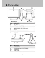
Page 8: ...tem Box Inside with Motherboard 10 Vesa Cover 11 Cables outlet No Description 1 Touch Screen 2 MSR 2 in 1 MSR Option 3 Power Button Power LED 4 Model No Label OS License Label 5 Stand 6 Cables outlet 7 Heat sink Top View Front View Rear View Side View ...

Page 9: ...3 No Description 1 DC 19V IN 2 Cash Drawer Port 3 USB x4 4 LAN 10 100 1000 5 COM x4 6 2nd VGA 7 DC 12V OUT 8 2 5 HDD 9 Parallel port 10 Line OUT Rear I O View ...

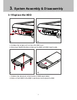
Page 10: ...c d a Unfasten the screws x2 to remove the HDD cover b Disconnect the HDD Cable and take out the HDD with HDD metal handle c Unfasten the screws x4 at both sides of HDD metal bracket d Slide out the HDD from the HDD metal bracket and replace the HDD a b ...

Page 11: ... the system box to access the motherboard See below a Unfasten the screws x11 on the back of system box b Press the Front bezel then separate top and bottom chassis L1 L2 c Remove the LCD rear cover d Unfasten the screw x8 fixing the motherboard and heatsink e Unfasten the screw x4 fixing the motherboard f cable unplug out the motherboard with metal I O bracket ...

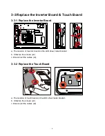
Page 12: ...rter Board a The location of Inverter board on the LCD sheet metal bracket b Unfasten the screws x2 c Disconnect the cables x3 3 3 2 Replace the Touch Board a The location of touch board on the LCD sheet metal bracket b Unfasten the screws x2 c Disconnect the cables x2 ...

Page 13: ... is washable and reusable Insert the filter inside the pocket in the rear cover bracket the handle backward the device and secure the filter with socket hole Draw out the filter from the pocket in the rear cover bracket Tip get the snap out of the socket hole first ...

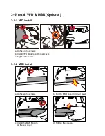
Page 14: ...1 VFD install a Unfasten the screws b Install VFD Module on the rear cover c Tighten the screws 3 5 2 MSR install c Install the MSR Module on the rear cover d Tighten the screws a Unfasten the screws b Pull the MSR cover from rear cover ...

Page 15: ...Option Intel BD82QM67 Platform Controller Hub BD82QM67 FCBGA 989 System Memory Default 1 x SO DIMM DDR3 1333 2GB Optional 2 x SO DIMM DDR3 1600 Maximum up to 8GB Graphic Memory Integrated graphics controller Intel HD Graphics 3000 LCD Touch Panel LCD Size 15 TFT XGA 1024x768 250cd m LCD panel Touch Screen 15 5 wire Resistive Zero Bezel Touch Panel Tilt Angle 0 80 Storage Device Hard Drive 1 x 2 5 ...

Page 16: ...perating Temperature 0 C 40 C 32 F 104 F Storage Temperature 20 C 60 C 4 F 140 F Operating Humidity 20 80 RH non condensing Storage Humidity 20 85 RH non condensing Dimension 80 tilt angle 366 W x 331 H x 210 D mm No MSR 419 W x 331 H x 210 D mm w MSR Display Head 366 W x 280 H x 64 5 D mm No MSR 419 W x 280 H x 64 5 D mm w MSR Footprint 249 W x 209 D mm Package Size 490 L x 390 W x 350mm H No MSR...

Page 17: ...11 5 Jumper Settings 5 1 HM 651 Motherboard Layout ...

Page 18: ...onnector CN13 VGA Connector CN14 DC Power Input Connector CON1 MSR connector CON2 Power output connector CON3 USB LAN Connector CON4 CASH drawing connector CON5 SATA POWER Connector J1 Internal USB connector J2 Internal USB connector J4 Power on SW J5 Reset SW J6 Battery socket J7 CCFL Connector J8 Keyboard connector J9 Speaker OUT J10 4 5 Wire touch connector JP1 SATA HD LAN POWER LED JP2 CMOS ME...

Page 19: ...13 5 3 Jumper Settings Panel Power selection JP5 Function JP1 1 2 2 3 3 3V VCC 5V Default setting 1 2 short CMOS CLEAR SIGNAL JP2 Function JP1 1 2 2 3 NORMAL CLEAR CMOS Default setting 1 2 short Note ...

Page 20: ... cash drawer port Please verify the pin assignment before installation Pin Signal 1 CASEOPEN2 2 CASH1_P 3 CASEOPEN 4 24V 5 CASH2_P 6 GND Cash Drawer Controller Register The Cash Drawer Controller use one I O addresses to control the Cash Drawer Cash Drawer Pin Assignment ...

Page 21: ... With easy to use pull down menus you can configure such items as Hard drives diskette drives and peripherals Video display type and display options Password protection from unauthorized use Power management features The settings made in the setup program intimately affect how the computer performs It is important therefore first to try to understand all the Setup options and second to make settin...

Page 22: ...olls backward through the values or options of the highlighted field F1 Displays General Help F2 Previous Value F3 Load optimized default setting F4 Saves and exits the Setup program Enter Press Enter to enter the highlighted sub menu Scroll Bar When a scroll bar appears to the right of the setup screen it indicates that here are more available fields not shown on the screen Use the up and down ar...

Page 23: ... Memory Information Displays the detected system memory information ME Firmware Information Displays the detected ME Firmware information System Date The date format is day month date year Day displays a day from Sunday to Saturday Month displays the month from January to December Date displays the date from 1 to 31 Year displays the year from 1999 to 2099 ...

Page 24: ...e format is hour minute second The time is based on the 24 hour military time clock For example 1 p m is 13 00 00 Hour displays hours from 00 to 23 Minute displays minutes from 00 to 59 Second displays seconds from 00 to 59 ...

Page 25: ...ur preference Setting incorrect field values may cause the system to malfunction Legacy OpROM support Launch LAN PXE OpROM Enable or disable boot option for legacy network devices Default Disabled ACPI Setting This section is used to set the Advanced Configuration and Power Interface CPU Configuration This section is used to configure the CPU It will also display detected CPU information SATA Conf...

Page 26: ... Configuration This section is used to configure the I O functions supported by the onboard Super I O chip H W Monitor This section is used to configure the hardware monitoring events such as temperature fan speed and voltages Sandybridge PPM Configuration This section is used to configure Sandy bridge PPM Configuration Parameters ACPI Setting This section is used to set the Advanced Configuration...

Page 27: ...e not effective with some OS Default Enabled ACPI Sleep State Select the highest ACPI sleep state the system will enter when the SUSPEND button is pressed Default S3 Suspend to RAM CPU Configuration This section is used to configure the CPU It will also display detected CPU information ...

Page 28: ...d for Hyper Threading technology When disabled only one thread per enabled core is enabled Default Enabled Hardware Prefetcher Turns on or off the MLC steamer prefetcher Default Enabled Intel Virtualization Technology When this field is set to Enable the VMM can utilize the additional hardware capabilities provided by Vanderpool technology Default Disabled ...

Page 29: ... Configuration This section is used to configure the SATA drives SATA Mode SATA Controller Enble or disable SATA Device Default Enabled SATA Mode Selection Determines how SATA controller s operate Default IDE ...

Page 30: ...24 AMT Configuration Configures the Active Management Technology function USB Configuration ...

Page 31: ...d Keeps USB devices available only for EFI applications Default Enabled EHCI Hand off This is a workaround for OSes that does not support EHCI hand off TheEHCI ownership change should be claimed by the EHCI driver Default Disabled Second Super IO Configuration This section is used to configure the I O functions supported by the onboard Super I O chip ...

Page 32: ...26 Serial Port 3 Configuration to Serial Port 6 Configuration Selects the IO IRQ setting of the I O devices ...

Page 33: ...e I O functions supported by the onboard Super I O chip Serial Port 1 Configuration to Serial Port 2 Configuration This section is used to configure the I O functions supported by the onboard Super I O chip Parallel Port Configuration Configures the parallel port ...

Page 34: ... as temperature fan speed and voltages System Temperature 1 to System Temperature 2 and CPU core Temperature Detects and displays the internal temperature of the system Fan1 Speed to Fan2 Speed Detects and displays the current system fan and CPU fan speed in RPM Revolutions Per Minute ...

Page 35: ...29 Vcore to 5V Detects and displays the output voltages Sandybridge PPM Configuration This section is used to configure Sandy bridge PPM Configuration Parameters ...

Page 36: ... Default Disabled CPU C3 Report Enable Disable CPU C3 ACPI C2 report to OS Default Disabled CPU C6 Report Enable Disable CPU C6 ACPI C6 report to OS Default Disabled CPU C7 Report Enable Disable CPU C7 ACPI C7 report to OS Default Disabled ...

Page 37: ...31 6 4 Chipset System Agent SA Configuration System Agent SA Parameters PCH IO Configuration PCH IO parameters ...

Page 38: ...s the Graphic chip setting of Intel IGFX Configuration Aperture Size Set Aperture Size Default 256MB DVNT Pre Allocation Internal graphic memory size Default 256M DVMT Total GFX Mem Select DVNT5 0 total graphic memory size Default 256M ...

Page 39: ...ction VFA modes will be supported only on primary display Default CRT Secondary IGFX Boot Display Select Secondary Display Device Default LFP LCD Panel Type Select LCD panel used by internal Graphics Device by selecting the appropriate setup item Default 1024x768 LVDS Panel color Depth Select the LFP Panel Color Depth Default 18 Bit LVDS Backlight Control Back Light Control Setting Default 100 ...

Page 40: ... LAN Controller Enables or disables onboard NIC Default Enable Wake on LAN Enable Enables or disables integrated LAN to wake the system Default Disabled Azalia Control Detection of the Azalia device Disabled Azalia will be unconditionally disabled ...

Page 41: ...Auto SLP_S4 Assertion Width Select a minimum assertion width of the SLP_S4 signal Default 4 5 Seconds Restore AC Power Loss Select AC power state when power is re applied after a power failure Default Power off 3G Wifi Module Type Allows BIOS to Select 3G Wifi Module with Without Voice function Default without Voice ...

Page 42: ... Boot Enables or disables the quiet boot function Default Enable Boot Option 1 and Boot Option 2 Selects the boot sequence of the hard drives Hard Drive BBS Priorities Sets the order of the legacy devices in this group ...

Page 43: ...37 6 6 Security Administrator Password Sets the administrator password User Password Sets the user password ...

Page 44: ...4 to save and exit Setup Discard Changes and Exit To exit the Setup utility without saving the changes select this field then press Enter You may be prompted to confirm again before exiting You can also press ESC to exit without saving the changes Load Optimized Default To restore lead default all values for all the setup options Confirm by selecting Yes to apply optimized default settings ...

Page 45: ...find every individual driver and utility that enables you to install the drivers in the Driver CD Please insert the Driver CD into the drive and double click on the index htm to pick up the models You can refer to the drivers installation guide for each driverin the Driver Manual List ...

Reviews: