background image

Copyright © 2013 NEXCOM International Co., Ltd. All Rights Reserved.

5

NCr-301-VHR User Manual 

Chapter 1: Product Introduction

Cable Installation

q

w

r

e

PHONE JACK

RJ45

y

t

u

i

q

w

r

e

PHONE JACK

RJ45

y

t

u

i

q

w

r

e

PHONE JACK

RJ45

y

t

u

i

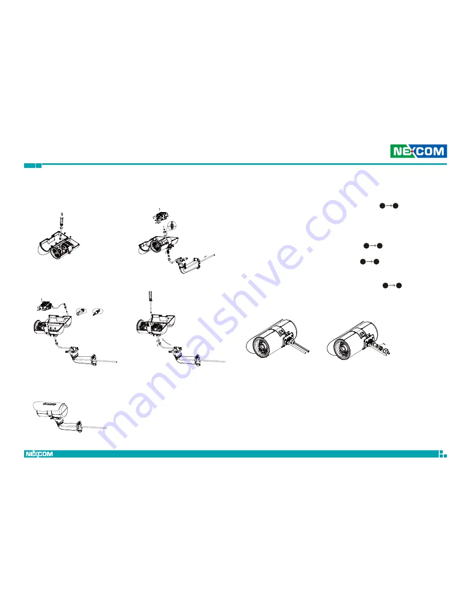
Cable Installation Steps:
1. Using a screwdriver, loosen the three mounting screws that hold the wall 

mount bracket, then take out the MB module ( 


).

2. Run the cable inside the wall mount bracket and out through the cable 

opening at the front, then slide the seal nut, tightening collar and main 
body of the waterproof connector onto the cable. Now run the cable 
through the opening at the bottom of the camera’s body, and place the 
gasket and screw nut through the cable ( 


).

3. Insert the RJ45 connector onto the end of the cable, and plug it into the 

corresponding port on the MB module ( 


). 

4. Place the MB module back to its original position and secure it with 

screws, then fasten the tightening collar and seal nut.

5. Install the camera onto the wall mount bracket ( 


).

1

3

5

7

8

6

4

2

u

i

Cable Wiring Description

1. The camera features two waterproof connectors, the left one in the 

diagram is for PoE connection, while the right one is for line in, line out, 
DC 12V/AC 24V and DI/O connections.

2. The right one features four wire holes. Please cover unused holes with 

sealing plugs to prevent water from entering.

3. Applicable cable diameter:


Ø 2.5~1.8mm (Right)


Ø 6.9~4.7mm (Left)

Line Out

Line in

DC12V/AC24V

DI/DO

Ethernet/PoE

Summary of Contents for NCr-301-VHR

Page 1: ...NEXCOM International Co Ltd NEXCOM International Co Ltd Published May 2013 www nexcom com Intelligent Digital Security IP Camera NCr 301 VHR User Manual ...

Page 2: ...cal Descriptions 4 DI O Pinout Assignment 4 Waterproof Connector Assembly 4 Cable Installation 5 Cable Wiring Description 5 Hardware Installation 6 Chapter 2 Camera Configuration Accessing the Camera s Configuration Menu Graphical User Interface 7 Installing NexCam Assistant 7 NexCam Assistant 10 Web Browser Internet Explorer 12 Configuring the Camera s Setting 13 Browsing Through the Configuratio...

Page 3: ...ection Zones 28 Alarm In Out Trigger 29 Alarm In Out Actions 29 Event Actions 30 When Motion Detection Triggered 30 When Alarm In Triggered 30 System 32 Audio 32 Audio Settings 32 User Management 33 Add Modify User Accounts 33 User List 33 SD Card Management 34 SD Card Information 34 File List 34 Date Time 35 Current Camera Time 35 Time Settings 35 Date Time Format 36 NTP Server 36 Firmware Upgrad...

Page 4: ...f NEXCOM International Co Ltd All other product names mentioned herein are registered trademarks of their respective owners Regulatory Compliance Statements This section provides the FCC compliance statement for Class B devices and describes how to keep the system CE compliant Declaration of Conformity FCC This equipment has been tested and verified to comply with the limits for a Class B digital ...

Page 5: ...olybrominated diphenyl Ethers PBDE 0 1 or 1 000ppm In order to meet the RoHS compliant directives NEXCOM has established an engineering and manufacturing task force to implement the introduction of green products The task force will ensure that we follow the standard NEXCOM development procedure and that all the new RoHS components and new manufacturing processes maintain the highest industry qual...

Page 6: ...es parts specified by the manufacturer Avoid using the system near water in direct sunlight or near a heating device The load of the system unit does not solely rely for support from the rackmounts located on the sides Firm support from the bottom is highly necessary in order to provide balance stability The network camera is provided with a battery powered real time clock circuit There is a dange...

Page 7: ...If the equipment is not used for a long time disconnect it from the power source to avoid damage by transient overvoltage 12 Never pour any liquid into an opening This may cause fire or electrical shock 13 Never open the equipment For safety reasons the equipment should be opened only by qualified service personnel 14 If one of the following situations arises get the equipment checked by service p...

Page 8: ...mation of the installed software operating system version application software etc A complete description of the problem The exact wordings of the error messages Warning 1 Handling the unit carry the unit with both hands and handle it with care 2 Maintenance to keep the unit clean use only approved cleaning products or clean with a dry cloth Conventions Used in this Manual Warning Information abou...

Page 9: ...VHR User Manual Preface Package Contents Placement sticker Hardware tool Sunshield Mounting accessory kit 2 axis cable concealed wall mount bracket Quick guide The NCr 301 VHR package contains the following accessories Dehumidifier packet Waterproof connector Wall mount base ...

Page 10: ...ils Binary code compatible for all 3MP 2MP models Separate parameters for easy customization Progressive scan and 3MP or HDTV 1080p image quality Multiple H 264 and MJPEG video streams Adjustable iris control to achieve best image quality WDR Wide Dynamic Range to overcome high contrast lighting environment Outdoor ready IP67 Face detection with extended applications Audio and human voice detectio...

Page 11: ... 1536 to 320 x 240 Video quality VBR 5 level adjustable CBR 30Kbps 10Mbps Frame rate 2048 x 1536 30 fps 1920 x 1080 60 fps 1280 x 720 60 fps 720 x 576 60 fps 720 x 480 60 fps 640 x 480 60 fps 320 x 240 60 fps Audio Audio streaming Two way Audio compression G 711 8KHz 16bit Audio input Line in Audio output Line out Network Interface 10 100 1000 Mbps Ethernet RJ 45 Supported protocols HTTP TCP IP UD...

Page 12: ...hapter 1 Product Introduction General Power consumption 20W max Weight 1 7kg Dimension 225 mm H φ121mm Operating Temp 40 C 55 C Humidity 90 RH no condensation Certification CE FCC Vandal resistant IK8 Outdoor capable IP67 built in heater Application SDK available for application development ...

Page 13: ...r Assembly Pin Description 1 ALM_IN 2 ALM_IN 3 ALM_out_NC 4 ALM_out_COM 5 ALM_out_NO 36PCS LED IR Illuminator Board Plate SB Module MB Module Dehumidifier packet Bracket Latch Line Out Line in DC12V AC24V Default Reset DI O Micro SD Ethernet PoE BNC No function 125O Rotate 360O Rotate DI O 54321 Screw nut Main body Strain relief Seal nut Waterproof connector Gasket Tightening collar ...

Page 14: ...of the camera s body and place the gasket and screw nut through the cable 3 Insert the RJ45 connector onto the end of the cable and plug it into the corresponding port on the MB module 4 Place the MB module back to its original position and secure it with screws then fasten the tightening collar and seal nut 5 Install the camera onto the wall mount bracket 1 3 5 7 8 6 4 2 u i Cable Wiring Descript...

Page 15: ...humidifier packet onto the metal bracket using the adhesive sticker on its back as depicted in the diagram below Close the camera s cover and ensure the clip is locked in position Install the sunshield and tighten a torx screw on the side of the cover Lock 4 Secure the connecting bracket to the camera s rear 5 Press and hold down the latch on the wall mount bracket and put it into the connecting b...

Page 16: ...et before proceeding You can access the camera via a web browser or NexCam Assistant software included with the camera The following information outlines the instructions for each method Installing NexCam Assistant 1 Locate the installation file NexCamAssistant Setup msi on the CD 2 Once located double click on the file to start the installation program 3 Click the Next button on the welcome scree...

Page 17: ...e click on the Browse button and locate the desired installation folder Next button Browse button Disk Cost button User accounts 7 Click on the Next button to continue 5 To check the available drives you can install the software to and their available and required disk space please click on the Disk Cost button 6 Specify which user accounts on the computer can access the program the options are Ev...

Page 18: ...erved 9 NCr 301 VHR User Manual Chapter 2 Camera Configuration Next button 8 Click on the Next button to begin installation Close button 9 Once the installation process is complete click on the Close button to finish A shortcut will be created on the desktop ...

Page 19: ...iguration menu via Internet Explorer You can also access the menu by double clicking the camera s IP address under Camera List 2 When the program is launched it will begin searching the network for the IP camera automatically the search will last for up to 90 seconds You can also manually search cameras by clicking on the Search button 3 Once the camera is discovered it will show the following inf...

Page 20: ...le cameras on the network To access all the cameras configuration menu simultaneously click on the Select All button to select all the cameras in the list then click the Home Page button Similarly you can access specific ones by ticking the camera s checkbox To deselect press the Clear All button to remove all the selection or specific ones by unchecking the checkbox Home Page Camera List Select A...

Page 21: ...name and 9999 default password 4 Once logged in you will see the main screen with video stream stream 3 Web Browser Internet Explorer Snapshot Takes a image snapshot from the camera you will be prompted to store the image file onto the computer s hard drive Start Stop Press to stop the live video press again to restart Viewer Views the live video of the camera Setup Options for configuring the IP ...

Page 22: ... to enter the configuration menu Setup eZoom Used to zoom in the live view video the options are 100 200 and 300 Setting 300 will zoom in at maximum level Focus Control Adjusts the camera s focus To adjust the focus automatically press the Auto Focus button To set the focus manually press the to focus far objects and to focus near objects Focus Zone Enables or disables display of focus zone in the...

Page 23: ...ettings are located on the left hand side of the interface clicking it will open their corresponding sub menu on the right The following are the camera settings available on the left hand side Video Video Stream Camera Settings Overlay Settings Privacy Mask Network TCP IP FTP SMTP Ports Events Motion Detection Alarm In Out Trigger Event Actions System Audio Settings User Management SD Card Managem...

Page 24: ...Configures the Bit Rate Control mode as VBR variable bit rate or CBR constant bit rate for the stream Target Bit Rate If the Bit Rate Control is set to CBR you can manually set the bit rate in this field the range is 30 20000kbit s GOP Length Configures the GOP length of the stream The options are 0 5 1 2 3 and 4 setting 0 5 seconds will yield the best video quality Video Video Stream This section...

Page 25: ...t Bit Rate If the Bit Rate Control is set to CBR you can manually set the bit rate in this field the range is 30 10000kbit s GOP Length Configures the GOP length of the stream The options are 0 5 1 2 3 and 4 setting 0 5 seconds will yield the best video quality Stream 3 MJPEG Resolution Displays the resolution of the video stream FrameRate Adjusts the frame rate of the video stream Setting 0 will ...

Page 26: ...e image the range is 0 255 with 0 being the lowest contrast Press the button to decrease the value or button to increase the value The default value is 128 Color Saturation Configures the color saturation of the image the range is 0 255 with 0 being the lowest saturation Press the button to decrease the value or button to increase the value The default value is 128 Sharpness Configures the sharpne...

Page 27: ...ance to suit the current lighting condition Fixed Outdoor Adjusts the white balance for outdoor daylight Incandescent Adjusts the white balance for indoor light Fluorescent Adjusts the white balance for fluorescent light Exposure Exposure Mode This option configures the anti flickering function of the camera If the image is suffering from flickering under fluorescent light selecting Auto will allo...

Page 28: ...plification in the drop down list The options are 4x 8x 16x and 32x A higher value will produce brighter images but may also increase image noise Enable Backlight Compensation Enables or disables backlight compensation function enable this option if an image in the camera is too dark Day Night Configures the day and night mode of the camera Auto Allows the camera to automatically sense the current...

Page 29: ...e on the bottom right corner Enable Text Enables or disables the Viewer to display text on the bottom left corner The text displayed can be configured in the field box Display Camera Name Enables or disables the Viewer to display the camera s name on the bottom left corner The name displayed can be configured in the Maintenance menu For information on Maintenance menu please refer to page 38 Save ...

Page 30: ...al Chapter 2 Camera Configuration Privacy Mask This section configures which area of the live video in Viewer will be masked for privacy A total of 3 privacy masks can be configured Settings Privacy Mask Color Selects the color of the privacy mask The available colors are Black and White ...

Page 31: ... to mask by holding down the mouse button and drag to make a rectangular square release the button once the desired area is covered 3 Press the Setting Area button in Enable mask zone 1 to set this area as mask 4 You will see the selected area turn black or white depending on which color was chosen This example uses black as the mask color Rectangular square Mask area 5 To create the second and th...

Page 32: ...HCP server Static IP Address To manually configure an IP address select this option and input the IP address subnet mask default gateway primary and secondary DNS server address Current Network Settings Displays the current IP address subnet mask default gateway primary and secondary DNS server address of the camera Save Save button to apply the configurations click on this button once all the set...

Page 33: ...on Username Specify the login username for the FTP server Password Specify the login password for the FTP server Test Remote FTP Server Server Status Displays the status of the test connection FTP Test Tests the network connection between the camera and FTP server Save Save button to apply the configurations click on this button once all the settings are confirmed for the new changes to take effec...

Page 34: ... Information Username Specify the login username for the SMTP mail server Password Specify the login password for the SMTP mail server Email Address From Specify the email address of the sender To Mail Address List Mail Address Specify the email address to send the email when an event is triggered by motion detection Press the Mail Test button to test the connection to this email Save Save button ...

Page 35: ...tion menu RTSP Stream 1 to 3 RTSP Port Configures the RTSP port number of stream 1 to 3 and displays the URL of stream 1 to 3 The range is 1025 65535 Default URL of Stream 1 rtsp cameraIP 8557 live stream1 Default URL of Stream 2 rtsp cameraIP 8556 live stream2 Default URL of Stream 3 rtsp cameraIP 8555 live stream3 Save Save button to apply the configurations click on this button once all the set...

Page 36: ...ideo in Viewer will be monitored for detecting motion Settings Enable Motion Detection Enables or disables motion detection function Sensitivity Configures the sensitivity of motion detection the sensitivity determines the amount of motion required to trigger an event the range is 1 to 100 with 1 being the least sensitive For more information on event please refer to Event Actions on page 30 ...

Page 37: ...nd specify the sensitivity level 2 In the live video screen below select the desired area for motion detection by clicking on the rectangular box The border of the box will turn red indicating that it is selected You can select multiple boxes up to 5x5 boxes can be selected 3 Press the Save button once all the desired areas are selected for the changes to take effect Highlighted box Area with moti...

Page 38: ...o the alarm output The options are Low and High Alarm Out Mode Specify the alarm out mode the options are User Mode and Event Mode When User Mode is selected the alarm output will be triggered based on user configurations When Event Mode is selected the alarm output will be triggered based on the configurations set in Event Actions For more information on Event Actions please refer to page 30 Alar...

Page 39: ...EG For information on configuring the FTP server please refer to FTP on page 24 Send Email Notification Check this option to send an email notifying the event for more information on configuring the email address please refer to SMTP on page 25 Alarm Output Check this option to activate the device connected to alarm output when motion detection is triggered When Alarm In Triggered Save Stream to S...

Page 40: ...he alarm event for more information on configuring the email address please refer to SMTP on page 25 Alarm Output Check this option to activate the device connected to alarm output when alarm in is triggered Save Save button to apply the configurations click on this button once all the settings are confirmed for the new changes to take effect Reset Reset button to discard all the settings applied ...

Page 41: ...audio in on the camera When enabled specify the volume in the Audio In Volume textbox The range is 1 100 Audio Out Enable Enables or disables audio out on the camera When enabled specify the volume in the Audio Out Volume textbox The range is 1 100 Save Save button to apply the configurations click on this button once all the settings are confirmed for the new changes to take effect Reset Reset bu...

Page 42: ...e a description for the account under the User Information field Access Level Administrator Has full control read write over every configuration menu item Operator Has full control read write over every configuration menu item in Video and Event only Viewer Only has access read to the live view of the camera main screen User List Displays user accounts available on the camera to edit an account s ...

Page 43: ...nstalled this section will display information on the availability of the SD card and the percentage of the total storage used Format Formats the SD card all data stored on the SD card will be erased if this option is used SD Card Overwrite Enables or disables overwrite protection for the SD card Press the Save button to apply the setting File List Displays the information of the folders and files...

Page 44: ...s option to synchronize the date and time with a NTP server Synchronize with Computer Time Select this option to synchronize the date and time to the computer connected to the camera Manually Setting Select this option to manually configure the date and time Time Zone Select the time zone relevant to your location in the drop down list Daylight Saving Select this option to enable daylight saving T...

Page 45: ...d DD MM YYYY Time Format Configures the format that the time will be displayed in The options are 12Hrs and 24Hrs NTP Server NTP Server Address If Synchronize with NTP Server is selected as the time mode type in the host name or IP address of the NTP server Save Save button to apply the configurations click on this button once all the settings are confirmed for the new changes to take effect Reset...

Page 46: ...s the current firmware version Update Specify the Firmware Image File to Upgrade To update the camera s firmware click on the Browse button and locate the firmware image file once the file is selected press the Update button to begin CAUTION CAUTION CAUTION The firmware update process will take around 15 minutes to complete during this time do not disconnect the network cable reset or power off th...

Page 47: ...setting back to factory default Camera Name Settings Camera Name Specify a name for the camera The name will be displayed in the upper left corner on the live video stream of the camera To enable this make sure the option Display Camera Name in the Overlay Settings menu is checked For information on the Overlay Settings menu please refer to page 20 Save Save button to apply the configurations clic...

Page 48: ...n org To stream the live video from the camera to VLC media player through the network please follow the instructions below 1 Locate and open VLC media player 2 Go to Media Open Network Stream 3 Enter the following RTSP URL rtsp 192 168 1 168 8557 live stream1 Note RTSP URL of stream 1 similarly you can view stream 2 and 3 of the camera by entering their corresponding URLs Please refer to Ports on...

Reviews: