


2
P.O. Box 1306
Newport Beach
California 92663
Phone: 714-751-0488
Fax: 714-957-1621
E-Mail: [email protected]
www.Newmarpower.com
Automation DC Power • Powering the Network
Quick Start Guide
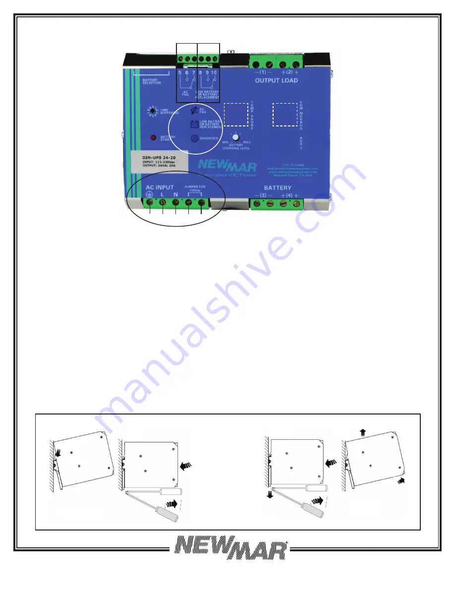
A) AC Input:
Wire Input Block (lettered left to right)
a) Earth Ground
b) AC Hot 230 VAC: no jumper installed across j1 & j2
AC Hot 115 VAC: wire jumper across j1 and j2
c) Neutral
j1 & j2) Jumper these two inputs for 115 VAC operation
See page
5
for details.
B) Battery Output:
two terminals each for plus and minus.
Utilize dual wiring when battery location is more than 15
feet from unit. See page
5
for details.
C) Battery Charge Current Limit:
Allows setting maximum
current fl ow to battery during recharge cycle, use when
low amp-hour batteries are applied to system to prevent
overheating when recovering dead batteries. Adjustment
range 20-100% of available charge current. (Available
charge current = unit output rating of 10 amps - load
demand. Note: the unit has a load priority circuit, all
produced power is made available to the load, remaining
power is available for battery charging). See page
6
for details.
D)
Battery Temperature Sensor (optional):
Plug in port
(RJ-45). See page
6
for details.
E) Communication Modbus:
contact factory for more
information
F)
Output to Load
, two terminals each for plus and minus,
utilize dual wiring when load is more than 15 feet from unit.
Note:
the unit has a load priority circuit, all produced power
is made available to the load, remaining power is avail-
able for battery charging. See page
5
for details.
G) Form C Contacts:
Activate upon:
a. AC power fail
b. Low battery or poor battery condition
See page
5
for details.
H) System Settings:
via plug-in jumper programing
terminals located on top of the unit.
a. Install jumper per illustration below (Table 1) to:
i. Select fl oat voltage per Battery Type and enable
Absorption Charge (see page page
7
for details)
ii. Enable Battery Test (Functional Setting)
iii. Disable/Enable Load Priority (Functional Setting)
See page
8
for details on functional settings.
A
B
A
B
Mounting DIN DC UPSto DIN Rail Removing DIN DC UPS from DIN Rail
Figure 1: Quick Start
Insert screwdriver in slot of bottom tab and twist to extend bracket
Ga
F
Gb
D
a b c j1 j2
A
J
1)
2)
3)
B
E
I
K
H