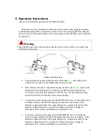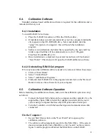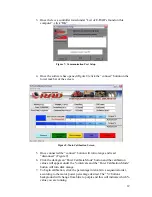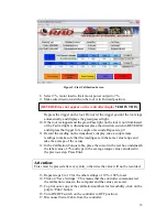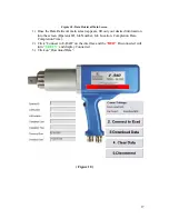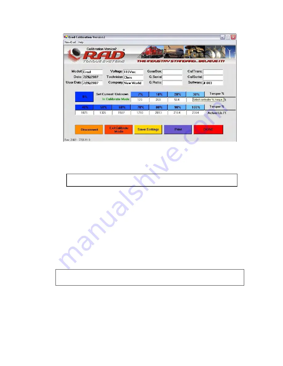
Figure 9: Start Calibration Screen
8.
Select 7%, motor load to limit motor power output to 7%.
9.
Make sure direction switch on the tool is in Forward position.
(REVERSE does not appear on the controller display
VERIFY THIS
)
Depress the trigger on the tool. Do not let the trigger go until the tool stops
automatically and displays the green passed light.
10.
If the tool is stopped and the green Pass light on the tool is not illuminated
or the Fail red light is illuminated, place the direction switch in REVERSE
and depress the trigger for a couple of seconds. Repeat step 9.
11.
Record the reading on the transducer’s display, take a couple more
readings to make sure that the readings are in the same value range and
take the average of the values.
12.
In the Calibration Torque table, place the cursor in the text box underneath
the label value of 7% and type in the average torque value calculated in
the previous step. Press Enter.
Attention:
Enter must be pressed after every entry, otherwise the value will not be recorded.
13.
Repeat steps 8 to 12 for the other settings of 10% - 100% load.
14.
Click on “Save Settings”. This means that the controller communicated
the calibration values to the computer and the values are saved.
15.
To print out a copy of the calibration numbers for traceability, click on the
purple “Print” button.
16.
Turn ON/OFF switch on the controller to OFF position;
17.
Disconnect Serial Cable from the controller.
13

