background image

INTRODUCTION

Capacities

T8.295

LA

T8.325

LA

T8.355

LA

T8.385

LA

System

Quantity

Recommended fluid

International

specification

Engine lubrication – with filter

25.0 L

(

6.6 US gal

)

NEW HOLLAND AMBRA

MASTERGOLD™ HSP ENGINE

OIL SAE 15W-40

ACEA E7 API CI-4

CES 20078

Cooling system

27.0 L

(

7.1 US gal

)

50%

of water and

50%

of

NEW HOLLAND AMBRA

ACTIFULL™ OT EXTENDED

LIFE COOLANT

ASTM D 6210

– Monoethylene

glycol

Transmission

172.0 L

(

45.4 US gal

)

NEW HOLLAND AMBRA

MASTERTRAN® ULTRACTION

SAE 10W-30 API

GL-4

Front axle – central reservoir

17.5 L

(

4.6 US gal

)

Front axle – final drives (hubs)
Class 4.75

4.3 L

(

1.1 US gal

)

Class 5.0

4.5 L

(

1.2 US gal

)

NEW HOLLAND AMBRA

HYPOIDE 140

SAE 10W-30, API

GL-4

Fuel tank – main (*)

359.6 L

(

79.1 UK gal

)

Fuel tank – auxiliary (*)

445.0 L

(

117.6 US gal

)

Petroleum diesel fuel (B7

Biodiesel)

-

Grease fittings

As required

NEW HOLLAND AMBRA GR-9

MULTI-PURPOSE GREASE

NLGI 2

Air conditioning – refrigerant
gas

2100 g

CNH R

EFRIGERANT

HFC-134

A

-

Air conditioning – compressor
lubricant

285 mL

S

ANDEN

SP-15 L

UBRICANT

-

(*) Theoretical fuel tank volume. Use only as a reference for the net volume of the tank.

NOTE:

To avoid damage to your machine, always use the same type of coolant. When you top up, use pure water.

If you change the additive used, clean the cooling system first.

NOTE:

Always check that the implement does not use more oil than is available in the tractor. The transmission

should have at least the minimum oil level in order to operate.

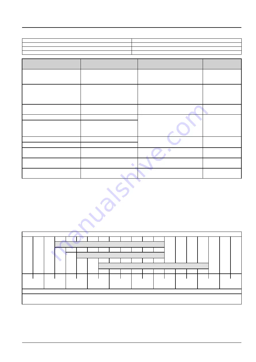
The correct engine oil viscosity grade is dependent upon ambient temperature. See the table below for the recom-
mended viscosity at different ambient air temperature ranges.

SAE 5W30

SAE 10W - 30

SAE 15W-40

-40 °C

-40 °F

-30 °C

-22 °F

-25 °C

(

-13 °F

)

-15 °C

(

5 °F

)

0 °C

32 °F

10 °C

50 °F

20 °C

68 °F

30 °C

86 °F

40 °C

104 °F

50 °C

122 °F

In environments with extreme air temperatures that require long periods of use of the machine, use

SAE 50

oil for

extremely high temperatures and

SAE 5W30

for extremely low temperatures.

47681318 16/05/2017

35

Summary of Contents for T8.295

Page 1: ... T8 295 T8 325 T8 355 T8 385TIER 3 Tractor Part number 47681318 English May 2017 2017 CNH Industrial Latin America LTDA All Rights Reserved SERVICE MANUAL 1 1 Part number 47681318 T8 295 T8 325 T8 355 T8 385 Tractor ...

Page 2: ...SERVICE MANUAL T8 295 18x4 with cab tier 3 T8 325 18x4 with cab tier 3 T8 355 18x4 with cab tier 3 T8 385 18x4 with cab tier 3 47681318 16 05 2017 EN Find manuals at https best manuals com ...

Page 3: ...cab tier 3 Latin America F2CFP614E H003 T8 325 18x4 with cab tier 3 Latin America F2CFP614D H003 T8 355 18x4 with cab tier 3 Latin America F2CFP614C H003 T8 385 18x4 with cab tier 3 Latin America F2CFP614B H003 47681318 16 05 2017 Find manuals at https best manuals com ...

Page 4: ... 21 113 Powershift transmission 21 2 21 135 Powershift transmission external controls 21 3 21 155 Powershift transmission internal components 21 4 21 200 Dropbox 21 5 21 900 Hydraulic pump drive 21 6 Four Wheel Drive 4WD system 23 23 202 Electro hydraulic control 23 1 23 314 Drive shaft 23 2 Front axle system 25 25 100 Powered front axle 25 1 25 102 Front bevel gear set and differential 25 2 25 10...

Page 5: ...lic service brakes 33 2 33 224 Trailer brake pneumatic control 33 3 Hydraulic systems 35 35 000 Hydraulic systems 35 1 35 102 Pump control valves 35 2 35 106 Variable displacement pump 35 3 35 114 Three point hitch control valve 35 4 35 204 Remote control valves 35 5 35 300 Reservoir cooler and filters 35 6 35 304 Combination pump units 35 7 Pneumatic system 36 36 100 Pneumatic system 36 1 Hitches...

Page 6: ...stem 55 8 55 020 Transmission speed sensors 55 9 55 045 Front axle control system 55 10 55 030 Service brake electrical system 55 11 55 032 Trailer brake electrical system 55 12 55 035 Remote control valve electric control 55 13 55 130 Rear three point hitch electronic control system 55 14 55 408 Warning indicators alarms and instruments 55 15 Platform cab bodywork and decals 90 90 100 Engine hood...

Page 7: ... 90 160 Cab interior trim and panels 90 6 47681318 16 05 2017 Find manuals at https best manuals com ...

Page 8: ...INTRODUCTION 47681318 16 05 2017 1 Find manuals at https best manuals com ...

Page 9: ...9 Safety rules 10 Safety rules 12 Safety rules Personal safety 13 Safety rules Ecology and the environment 25 Torque Minimum tightening torques for normal assembly 26 Torque Standard torque data for hydraulics 31 Basic instructions Shop and assembly 33 Capacities 35 See content for specific models 47681318 16 05 2017 2 Find manuals at https best manuals com ...

Page 10: ...ld washer Road speed Rear hitch lower Engine Oil Pressure Windscreen wash wipe Differential Lock Hydraulic lift height threshold Engine Coolant Temperature Heating temperature control Rear axle oil temperature Hydraulic lift disabled Coolant Level Cab recirculation fan Trans Oil Pressure Transmission filters and hydraulic filters Machine lights Air conditioner Auxiliary Front Wheel Drive AFWD oper...

Page 11: ...ata specifications the functional data how it works the diagnostic data fault codes and troubleshooting and the service data remove install adjust etc By integrating SAP coding into technical information you will be able to search and retrieve just the right piece of technical information you need to resolve that customer s concern on his machine This is made possible by attaching 3 categories to ...

Page 12: ...stems on the machine Each Section is identified by a number 00 35 55 etc The Sections included in the manual will depend on the type and function of the machine that the manual is written for Each Section has a Contents page listed in alphabetic numeric order This table illustrates which Sections could be included in a manual for a particular product PRODUCT Tractors Vehicles with working arms bac...

Page 13: ...2 Separation X 73 Residue handling X 74 Cleaning X 75 Soil preparation Finishing 76 Secondary cleaning Destemmer 77 Seeding X 78 Spraying X 79 Planting X 80 Crop storage Unloading X 82 Front loader and bucket X X 83 Telescopic single arm X X 84 Booms dippers and buckets X X 86 Dozer blade and arm X X 88 Accessories X X X X X 89 Tools X X X X X 90 Platform cab bodywork and decals X X X X 47681318 1...

Page 14: ...e 10 001 TECHNICAL DATA ENGINE Engine and crankcase General specification 10 001 D 40 A 10 4 FUNCTIONAL DATA ENGINE Engine and crankcase Dynamic description 10 001 C 30 A 10 6 SERVICE ENGINE Engine and crankcase Remove 10 001 F 10 A 10 8 DIAGNOSTIC ENGINE Engine and crankcase Troubleshooting 10 001 G 40 A 10 10 INDEX The Chapter Index lists in alphabetical order all the types of information called...

Page 15: ...the chapters of the service manual After B there may be some additional information In this case it shows 01 which represents the Front block cover These options may be front rear left right hydraulic mechanical etc C corresponds to the type of information listed in the chapter contents Technical Data Functional Data Diagnos tic or Service A and B are also shown in the page numbering on the page f...

Page 16: ...by parts and or components not approved by the manu facturer including those used for the servicing or repair of the product manufactured or marketed by the manufacturer In any case no warranty is given or attributed on the product manufactured or marketed by the manufacturer in case of damages caused by parts and or components not approved by the manufacturer The manufacturer reserves the right t...

Page 17: ...sence of voltages exceeding 48 60 V verify the efficiency of the ground and mass electrical connections Ensure that hands and feet are dry and use isolating foot boards Workers should be properly trained to work with electricity Do not smoke or start an open flame close to batteries and any fuel material Place soiled rags with oil diesel fuel or solvents in specially provided anti fire containers ...

Page 18: ...y approved by NEW HOLLAND Do not modify the fuel system or hydraulic system unless approved by NEW HOLLAND Any unauthorized modifi cation will compromise warranty assistance and may affect engine operation and life span For engine equipped with an electronic control unit Do not weld on any part of the equipment without removing the control unit Remove the in case of work requiring heating over 80 ...

Page 19: ...ry The color associated with WARNING is ORANGE CAUTION indicates a hazardous situation that if not avoided could result in minor or moderate injury The color associated with CAUTION is YELLOW FAILURE TO FOLLOW DANGER WARNING AND CAUTION MESSAGES COULD RESULT IN DEATH OR SERIOUS INJURY Machine safety NOTICE Notice indicates a situation that if not avoided could result in machine damage or property ...

Page 20: ...ses with increasing speed as the weight of the towed load increases especially on hills and slopes Rear upset can result if pulling from wrong location on tractor Hitch only to the drawbar Use three point hitch only with the implements designed for its use not as a drawbar Do not look directly into the front or rear HID high intensity discharge lamps Eye damage can occur Do not tamper with the bal...

Page 21: ...ine can start with the transmission in gear Do not connect or short across terminals on the starter solenoid Attach jumper cables as described in the manual Starting in gear may cause death or serious injury Always keep windows mirrors all lighting and Slow Moving Vehicle SMV emblem clean to provide the best possible visibility while operating the machine Operate controls only when seated in the o...

Page 22: ...w pressure to escape before completely removing the cap Replace damaged or worn tubes hoses electrical wiring etc Engine transmission exhaust components and hydraulic lines may become hot during operation Take care when servicing such components Allow surfaces to cool before handling or disconnecting hot components Wear protective equipment when appropriate When welding follow the instructions in ...

Page 23: ... materials trash debris bird nests or flammable material can ignite on hot surfaces Always have a fire extinguisher on or near the machine Make sure the fire extinguisher s is maintained and serviced according to the manufacturer s instructions At least once each day and at the end of the day remove all trash and debris from the machine especially around hot components such as engine transmission ...

Page 24: ...ntidote internal Drink large quantities of water or milk Do not induce vomiting Seek medical attention immedi ately Keep out of reach of children and other unauthorized persons Instructional seat safety Passengers are not permitted to ride on the machine The instructional seat is to be used only when training a new operator or when a service technician is diagnosing a problem When required for the...

Page 25: ...nd have operational hazards Attach only the primary PTO drive shaft coupling to the tractor PTO output shaft Never use a spline adapter Match the right tractor PTO spline and speed with the PTO driveshaft provided with an implement This will assure proper geometry and operating speed Never operate 540 RPM implements at 1000 RPM Never operate 1000 RPM implements at 540 RPM Use of PTO adapters will ...

Page 26: ...re MUST BE REPLACED The mounting or suspension for the protective structure operator seat and suspension seat belts and mounting components and wiring within the operator s protective system MUST be carefully inspected for damage All damaged parts MUST BE REPLACED DO NOT WELD DRILL HOLES ATTEMPT TO STRAIGHTEN OR REPAIR THE PROTECTIVE STRUCTURE MOD IFICATION IN ANY WAY CAN REDUCE THE STRUCTURAL INT...

Page 27: ...our local utilities or authorities as appropriate to determine the locations of services Make sure the machine has sufficient clearance to pass in all directions Pay special attention to overhead power lines and hanging obstacles High voltage lines may require significant clearance for safety Contact local authorities or utilities to obtain safe clearance distances from high voltage power lines Re...

Page 28: ...s Loader buckets forks etc or other lifting handling or digging equipment and its load will change the center of gravity of the machine This can cause the machine to tip on slopes or uneven ground Load items can fall off the loader bucket or lifting equipment and crush the operator Care must be taken when lifting a load Use proper lifting equipment Do not lift load higher than necessary Lower load...

Page 29: ...he implement Do not exceed implement transport speed or the speed rating on the implement tires Review the implement s Oper ators Manual for specifications Objects ejected by some implements or tools for example a rotary mower may harm bystanders outside the field Stones may be thrown further than the discharged crop Projectiles can be thrown outside the field and strike unprotected individuals fo...

Page 30: ...e tractor to roll over Always check the condition and rating of ramps before use Do not operate the tractor without using the seat restraint In the event of a roll over or tip over the ROPS cab or ROPS structure is only fully effective if the driver remains attached to the seat Do not operate the tractor beyond its limits of dynamic stability High speed abrupt maneuvers or fast and sharp cornering...

Page 31: ... external forces to the hose The hose may fail and cause injury Keep all persons away from the working area Mechanisms controlled by fluid power can become hazardous if a hose fails Lifted mechanisms can fall to the ground machine steering may fail etc Stay clear of a pressurized hose assembly that has blown apart Hose fittings can be thrown off at high speed and a loose hose can whip around with ...

Page 32: ...ot allow coolant mixtures to get into the soil Collect and dispose of coolant mixtures properly The air conditioning system contains gases that should not be released into the atmosphere Consult an air condi tioning specialist or use a special extractor to recharge the system properly Repair any leaks or defects in the engine cooling system or hydraulic system immediately Do not increase the press...

Page 33: ...in 25 N m 217 lb in 26 N m 234 lb in 35 N m 311 lb in 17 N m 151 lb in 24 N m 212 lb in M10 37 N m 27 lb ft 49 N m 36 lb ft 52 N m 38 lb ft 70 N m 51 lb ft 33 N m 25 lb ft 48 N m 35 lb ft M12 64 N m 47 lb ft 85 N m 63 lb ft 91 N m 67 lb ft 121 N m 90 lb ft 58 N m 43 lb ft 83 N m 61 lb ft M16 158 N m 116 lb ft 210 N m 155 lb ft 225 N m 166 lb ft 301 N m 222 lb ft 143 N m 106 lb ft 205 N m 151 lb ft...

Page 34: ...9 N m 343 lb in 18 N m 163 lb in 27 N m 240 lb in M10 40 N m 30 lb ft 54 N m 40 lb ft 57 N m 42 lb ft 77 N m 56 lb ft 37 N m 27 lb ft 53 N m 39 lb ft M12 70 N m 52 lb ft 93 N m 69 lb ft 100 N m 74 lb ft 134 N m 98 lb ft 63 N m 47 lb ft 91 N m 67 lb ft M16 174 N m 128 lb ft 231 N m 171 lb ft 248 N m 183 lb ft 331 N m 244 lb ft 158 N m 116 lb ft 226 N m 167 lb ft M20 350 N m 259 lb ft 467 N m 345 lb...

Page 35: ...ft 7 16 48 N m 36 lb ft 65 N m 48 lb ft 68 N m 50 lb ft 91 N m 67 lb ft 50 N m 37 lb ft 71 N m 53 lb ft 1 2 74 N m 54 lb ft 98 N m 73 lb ft 104 N m 77 lb ft 139 N m 103 lb ft 76 N m 56 lb ft 108 N m 80 lb ft 9 16 107 N m 79 lb ft 142 N m 105 lb ft 150 N m 111 lb ft 201 N m 148 lb ft 111 N m 82 lb ft 156 N m 115 lb ft 5 8 147 N m 108 lb ft 196 N m 145 lb ft 208 N m 153 lb ft 277 N m 204 lb ft 153 N...

Page 36: ...85 lb ft 153 N m 113 lb ft 74 N m 55 lb ft 104 N m 77 lb ft 9 16 117 N m 86 lb ft 156 N m 115 lb ft 165 N m 122 lb ft 221 N m 163 lb ft 106 N m 78 lb ft 157 N m 116 lb ft 5 8 162 N m 119 lb ft 216 N m 159 lb ft 228 N m 168 lb ft 304 N m 225 lb ft 147 N m 108 lb ft 207 N m 153 lb ft 3 4 287 N m 212 lb ft 383 N m 282 lb ft 405 N m 299 lb ft 541 N m 399 lb ft 261 N m 193 lb ft 369 N m 272 lb ft 7 8 4...

Page 37: ...8 4 Grade Identification Grade Corner Marking Method 1 Flats Marking Method 2 Clock Marking Method 3 Grade A No Notches No Mark No Marks Grade B One Circumferential Notch Letter B Three Marks Grade C Two Circumferential Notches Letter C Six Marks 47681318 16 05 2017 30 ...

Page 38: ...0 15 lb ft 6 9 5 mm 3 8 in 9 16 18 29 33 N m 21 24 lb ft 20 27 N m 15 20 lb ft 8 12 7 mm 1 2 in 3 4 16 47 54 N m 35 40 lb ft 34 41 N m 25 30 lb ft 10 15 9 mm 5 8 in 7 8 14 72 79 N m 53 58 lb ft 47 54 N m 35 40 lb ft 12 19 1 mm 3 4 in 1 1 16 12 104 111 N m 77 82 lb ft 81 95 N m 60 70 lb ft 14 22 2 mm 7 8 in 1 3 16 12 122 136 N m 90 100 lb ft 95 109 N m 70 80 lb ft 16 25 4 mm 1 in 1 5 16 12 149 163 ...

Page 39: ...ngs When installing ORFS fittings thoroughly clean both flat surfaces of the fittings 1 and lubricate the O ring 2 with light oil Make sure both surfaces are aligned properly Torque the fitting to specified torque listed throughout the repair manual NOTICE If the fitting surfaces are not properly cleaned the O ring will not seal properly If the fitting surfaces are not properly aligned the fitting...

Page 40: ...allation tool Do not tap the seal with a hammer or mallet 6 While you insert the seal check that the seal is perpendicular to the seat When the seal settles make sure that the seal makes contact with the thrust element if required 7 To prevent damage to the seal lip on the shaft position a protective guard during installation operations O ring seals Lubricate the O ring seals before you insert the...

Page 41: ...battery ground cable from the machine battery The electronic monitoring system and charging system will be damaged if this is not done 5 Remove the battery ground cable Reconnect the cable when you complete welding WARNING Battery acid causes burns Batteries contain sulfuric acid Avoid contact with skin eyes or clothing Antidote external Flush with water Antidote eyes flush with water for 15 minut...

Page 42: ...r conditioning refrigerant gas 2100 g CNH REFRIGERANT HFC 134A Air conditioning compressor lubricant 285 mL SANDEN SP 15 LUBRICANT Theoretical fuel tank volume Use only as a reference for the net volume of the tank NOTE To avoid damage to your machine always use the same type of coolant When you top up use pure water If you change the additive used clean the cooling system first NOTE Always check ...

Page 43: ...tite 545 Torque Standard torque data for hydraulics 32 NEW HOLLAND AMBRA MASTERGOLD HSP ENGINE OIL SAE 15W 40 Capacities 35 NEW HOLLAND AMBRA ACTIFULL OT EXTENDED LIFE COOLANT Capacities 35 NEW HOLLAND AMBRA MASTERTRAN ULTRACTION Capacities 35 NEW HOLLAND AMBRA HYPOIDE 140 Capacities 35 NEW HOLLAND AMBRA GR 9 MULTI PURPOSE GREASE Capacities 35 CNH Refrigerant HFC 134a Capacities 35 Sanden SP 15 Lu...

Page 44: ...SERVICE MANUAL Engine T8 295 18x4 with cab tier 3 T8 325 18x4 with cab tier 3 T8 355 18x4 with cab tier 3 T8 385 18x4 with cab tier 3 47681318 16 05 2017 10 ...

Page 45: ...10 001 Engine and crankcase 10 1 10 114 Pump drives 10 2 10 202 Air cleaners and lines 10 3 10 216 Fuel tanks 10 4 10 310 Aftercooler 10 5 10 400 Engine cooling system 10 6 10 414 Fan and drive 10 7 47681318 16 05 2017 10 ...

Page 46: ...CONSUMABLES INDEX Consumable Reference PAGE Loctite 515 Accessory drive Install 10 2 16 NEW HOLLAND AMBRA AGRIFLU Engine cooling system Filling 10 6 15 47681318 16 05 2017 10 ...

Page 47: ...47681318 16 05 2017 10 ...

Page 48: ...Engine 10 Engine and crankcase 001 T8 295 18x4 with cab tier 3 T8 325 18x4 with cab tier 3 T8 355 18x4 with cab tier 3 T8 385 18x4 with cab tier 3 47681318 16 05 2017 10 1 10 001 1 ...

Page 49: ...Contents Engine 10 Engine and crankcase 001 SERVICE Engine Remove 3 Install 18 47681318 16 05 2017 10 1 10 001 2 ...

Page 50: ... 1 Disconnect the hydraulic cooling line connection on the right side from oil cooler NOTE Be prepared to collect some hydraulic oil by placing a pan under the fitting RCPH10CCH771AAB 1 2 Disconnect the hydraulic line 1 on the left side to oil cooler Disconnect the engine cooling fan drive harness connector 3 3 Disconnect the air conditioning low pressure hose to line fitting return from condenser...

Page 51: ...e turbocharger clamp 1 9 Loosen the air cooler inlet hose clamp 2 10 Remove the tube 3 Set the tube aside 11 Repeat for the right side air to air tube from the cooler to the intake manifold not shown RCPH10CCH775AAB 5 12 Remove and discard O ring face seal from elbow RCPH10CCH778AAB 6 13 Remove and discard O ring face seal from elbow RCPH10CCH777AAB 7 47681318 16 05 2017 10 1 10 001 4 ...

Page 52: ...he engine hose RCPH10CCH580AAB 9 16 Remove the nuts 1 and disengage the engine heater grid cables 2 3 to the fuse block 17 Disconnect the harness connector 4 for the 12 V auxiliary power connection RCPH10CCH779AAB 10 18 Disconnect the ECM engine control module connec tor 1 by moving the locking handle 2 from the right locked position to the left unlocked position RCPH10CCH780AAB 11 47681318 16 05 ...

Page 53: ...the A C compressor clutch 2 21 Remove the upper left A C compressor bolt and re move the ground wire 3 RCPH10CCH782AAB 13 22 Disconnect the harness connectors to the A C high pressure switch 1 and the engine cooling fan drive 2 RCPH10CCH783AAB 14 23 Disconnect the harness connector 1 to the grid heater controller RCPH10CCH784AAB 15 47681318 16 05 2017 10 1 10 001 6 ...

Page 54: ...AB 16 25 Loosen the nut 1 and disconnect the fuel supply line to the EMC cooler RCPH10CCH787AAB 17 26 Disengage the clamp 1 and disconnect the fuel re turn hose 2 from the pipe RCPH10CCH786AAB 18 27 Remove the nut 1 and disengage the alternator out put cable 2 RCPH10CCH788AAB 19 47681318 16 05 2017 10 1 10 001 7 ...

Page 55: ...olenoid 1 30 Raise the locking wire 2 and disconnect the heater supply connector 3 from the valve 31 Repeat for the outlet hose connection located on the right side of the valve RCPH10CCH790AAB 21 32 Disconnect the main engine to chassis harness con nector RCPH10CCH791AAB 22 33 Disconnect the auxiliary engine to chassis harness connectors 1 RCPH10CCH792AAB 23 47681318 16 05 2017 10 1 10 001 8 ...

Page 56: ...g and disconnect the hydraulic oil line 1 right side of engine RCPH10CCH798AAB 25 36 Disconnect the water in fuel sensor connector 1 from the primary fuel filter RCPH10CCH794AAB 26 37 Loosen the nuts 1 and disconnect the A C lines lo cated between the hood support and the cab RCPH10CCH799AAB 27 47681318 16 05 2017 10 1 10 001 9 ...

Page 57: ...nut 1 and disengage the cables from the starter RCPH10CCH797AAB 29 40 Remove the plug 1 remove the attaching screw 2 and remove the starter solenoid wire 3 RCPH10CCH818AAB 30 41 Loosen the hose clamp 1 and disconnect the fill hose elbow 2 RCPH10CCH795AAB 31 47681318 16 05 2017 10 1 10 001 10 ...

Page 58: ...ight sides RCPH10CCH572AAB 33 44 Properly support the bracket and remove the four bolts 1 securing the bracket to the hood support Re move the assembly Set the assembly aside RCPH10CCH037BAB 34 45 Loosen the clamp 1 and disconnect the coolant fill line 46 Loosen the nuts 2 and 3 and disconnect the cab heater supply and return lines 47 Disengage the clamp 4 and remove the air bleed hose 48 Remove t...

Page 59: ... dosing valve RCPH10CCH801AAB 37 51 Disconnect the DEF supply and return hoses 1 NOTE Squeeze the locking tabs 2 together and pull straight upward on the elbow RCPH10CCH359AAB 38 52 Remove the clamp 1 at the turbocharger Repeat for clamp at the other end of the pipe 2 Remove the pipe and set aside RCPH10CCH806AAB 39 47681318 16 05 2017 10 1 10 001 12 ...

Page 60: ... 54 Disengage the engine blow by hose clamp 1 at the intake pipe Disconnect from the intake pipe RCPH10CCH805AAB 41 55 Disengage the engine blow by hose clamp 1 at the engine Remove the pipe and set aside RCPH10CCH807AAB 42 56 Loosen the clamp 1 securing the intake pipe elbow to the turbocharger Disconnect from the turbo RCPH10CCH809AAB 43 47681318 16 05 2017 10 1 10 001 13 ...

Page 61: ...This as a preview PDF file from best manuals com Download full PDF manual at best manuals com ...

Reviews: