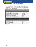
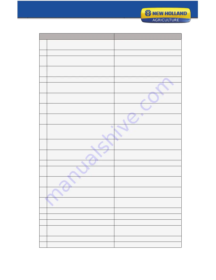
New Holland Gasoline Portable Air Compressor Operation Manual Download Page 17

17

troubleshooting

Possible Cause

Possible Solution

A Low Oil Shutdown

Fill engine with the adequate amount 

of oil.

B Cold Engine

Choke engine to start.

C No Fuel

Add gas to engine. Make sure fuel 

shutoff valve is open

D Engine not turned ON

Place ON/OFF switch in the ON 

position.

E Spark plug wire not attached

Attach spark plug wire to spark plug.

F Compressor viscosity too high for 

ambient temperature.

Drain existing lubricant and refill with 

proper lubricant.

G Belt tension too tight or sheaves not 

aligned.

Check tension/ alignment.

H Air leaks in discharge piping.

Check tubing connections, Tighten 

joints or replace as required.

I

Compressor components leaky, 

broken, loose.

Inspect components. Clean or 

replace as required.

J

Loose flywheel or motor pulley, 

excessive end play in motor shaft or 

loose drive belts.

Check flywheel, motor pulley, and 

crankshaft drive belt tension/align-

ment. Replace or repair as required.

K Leaking check valve or check valve 

seat blown out.

Replace check valve.

L Clogged or dirty inlet and/or dis-

charge line.

Clean or replace.

M Defective safety/relief valve.

Replace.

N Pressure switch unloader leaks or 

does not work.

Realign stem or replace.

O Inadequate ventilation around 

flywheel.

Relocate compressor for better 

airflow.

P Leaking, broken or worn inlet un-

loader parts at check valve.

Inspect parts and replace as 

required.

Q Excessive condensation in receiver 

tank.

Drain receiver tank.

R Detergent lubricant in crankcase.

Replace with proper lubricant.

S Light duty cycle.

Increase duty cycle.

T Lubricant level too high.

Drain excess lubricant.

U Worn cylinder finish.

Deglaze cylinder with 180 grit 

flex-hone.

V Low pressure inlet valve leaking.

Inspect, clean or repair as required.

W High pressure inlet valve leaking.

Inspect, clean or repair as required.

Summary of Contents for Gasoline Portable Air Compressor

Page 1: ...operation manual ...

Page 2: ...ut incurring any obliga tion to install them on units previously sold Attention Read through the complete manual prior to the initial use of your compressor introduction Quick Facts Engine Oil Engine is shipped without oil Fill before starting Use SAE 10W 30 motor oil Pump Oil Check pump oil level before starting Use SAE 30W non detergent pump oil Air Filter Replacement air filter part number is A...

Page 3: ...line 1 855 850 6668 for information on servicing always provide the product model and identification numbers You will need to locate the model and serial number for the machine and record the information in the places provided below Date of Purchase Dealer Name Dealer Phone Product Identification Numbers Model Number Serial Number ...

Page 4: ...eadly NEVER add fuel when the product is operating or hot NEVER directly inhale compressed air NEVER over pressurize the receiver tank or similar vessels beyond design limits NEVER use a receiver tank or similar vessels that fail to meet the design requirements of the compressor NEVER drill into weld or otherwise alter the receiver tank or similar vessels NEVER remove adjust bypass change modify o...

Page 5: ...ivery receipts that have been signed with out a notation of damage or missing parts are considered to be delivered clear Subsequent claims are then considered to be concealed damage claims Settle damage claims directly with the transportation company If you discover damage after receiving the air compressor concealed damage the carrier must be notified within 15 days of receipt and an in spection ...

Page 6: ...l tank pressure attach hose to this port Thread size is NPT 7 Tank Drain Location of tank drains Drain tank daily or after each use 8 Regulator Adjust outlet pressure not to exceed pressure rating of the tool 9 Quick Connect This is a quick connect 10 Unloader Lift knob to relieve pressure when starting the engine 11 ASME Safety Valve This valve automatically releases air if the tank pressure exce...

Page 7: ...7 s assembly Attach rubber feet as shown Item Description Qty Rubber Foot 4 5 16 X 1 1 2 Flange Bolt 4 5 16 Flange Nut 4 ...

Page 8: ... start your engine 5 Once the engine has started move the pressure relief knob to the engine run position Engine Start Engine Run CAUTION Unusual noise or vibration indicates a problem Do not continue to operate until you identify and correct the source of the problem CAUTION Do not attach air tools to open end of the hose until start up is completed and the unit checks out OK 6 Run the unit for 3...

Page 9: ...um quality does not contain detergents contains only anti rust anti oxidation and anti foam agents as additives has a flashpoint of 440o F 227o C or higher and has a auto ignition point of 650o F 343o C or higher See the petroleum lubricant viscosity table below The table is intended as a general guide only Heavy duty operating conditions require heavier viscosities Refer specific operating condit...

Page 10: ...regulations NOTE Take note of the position and locations of parts during disas sembly to make reassembly easier The assembly sequences and parts illustrated may differ for your particular unit Daily or before each operation Check lubrication levels Fill as needed Drain receiver tank condensation Check for unusual noise or vibration Ensure belt guards and covers are securely in place Ensure area ar...

Page 11: ...sted a 5 pound force applied to the belt between the motor pulley and the pump will deflect the belt about 1 2 To Adjust Drive Belt Remove belt guard 1 Loosen the four fasteners holding the engine to the compressor 2 Shift the engine in the proper direction The belt must be properly 3 aligned when adjustment is made To align belt visually center engine pulley to compressor pulley 4 If necessary mo...

Page 12: ...12 kits service parts Air filter Part AB2281000 Non detergent Oil Part 4043 ...

Page 13: ... New Holland Decal 1 15 Rubber Foot 4 16 Warning Hot Decal 1 17 Drain Valve 2 18 Honda Bushing 1 Item Description Part Qty 19 Idle Solenoid 1 20 Rubber Grip 2 21 Unloader 100 130 psi 1 22 5 8 Compression Sleeve 2 23 5 8 Compression Nut 2 24 Copper Tube 1 25 1 2 Elbow 1 26 Quick Connect 1 27 Regulator 1 28 1 4 Pipe Tee 1 29 Hex Plug 1 30 2 1 2 Bottom Mount Gauge 1 31 1 4 Street Tee 1 32 Safety Valv...

Page 14: ...16 Crankcase 1 17 Cylinder Bolt M6 x 20mm SHCS 6 18 Oil Drain Plug 1 19 Crankcase Bottom Bolt M5 x 15mm HHSS 8 20 Oil Pan 1 Item Description Part Qty 21 Oil Pan Gasket 1 22 Crankshaft 1 23 Cover D E 1 24 Oil Seal 1 25 Screw Reverse Thread 1 26 Flywheel Washer 1 27 Flywheel 280mm 1 28 Bearing Housing Bolt M6 x 15mm SHCS 8 29 Connecting Rod 2 30 Circlip 4 31 Wrist Pin 2 32 Piston Aluminum 2 33 Pisto...

Page 15: ...15 pneumatic schematic diagram Item 46850 ...

Page 16: ...se Engine does not start A B C D E Air delivery drops off H I J L M N P Compressor does not come up to speed F G J K Compressor is slow to come up to speed F G J K L Compressor will not unload cycle H L N P Compressor will not unload when stopped H L N P Excessive starting or stopping N Q S Moisture in crankcase milky substance in oil R Oil in discharge air T Safety relief valve pops L M N Low int...

Page 17: ...haft or loose drive belts Check flywheel motor pulley and crankshaft drive belt tension align ment Replace or repair as required K Leaking check valve or check valve seat blown out Replace check valve L Clogged or dirty inlet and or dis charge line Clean or replace M Defective safety relief valve Replace N Pressure switch unloader leaks or does not work Realign stem or replace O Inadequate ventila...

Page 18: ...If you need assistance with the assembly or operation of your Generator please call 1 855 850 6668 ...

Reviews: