background image

Operation

214811

30

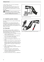
Move the bale spike into position at the end of the bale.
Make sure the bale spike is centered left to right and top to

bottom with relation to the bale.
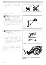
Drive forward slowly into the bale until spike fully

penetrates the bale.

Fig. 67 Drive forward slowly into the bale until spike fully

penetrates the bale.

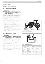
Tilt the bale back, lift the load carefully. Raise loader only

enough for clearance under bale. Move bale slowly and

carefully until ready to unload.

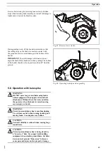
Fig. 68 Tilt the bale forward to level position and place bale on

the ground.

Tilt the bale forward to level position and place bale on the

ground.
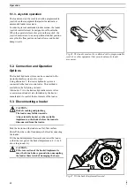
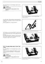
Carefully reverse unit away from bale.

Fig. 69 Carefully reverse unit away from bale.

5.7. Coupling and uncoupling

implements

5.7.1. Uncoupling implements, Euro 8

Tool carrier

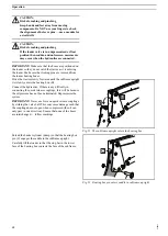
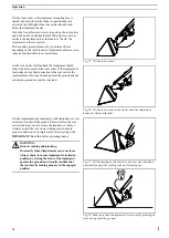
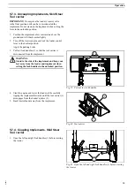
Raise the loader off the ground and position the implement

level to the ground.
Turn off the tractor engine and lock the loader control lever

in the neutral position.
Apply the parking brake.

Fig. 70 Raise the loader off the ground, turn off the engine,

lock control lever in neutral position.

Summary of Contents for 611TL

Page 1: ...OPERATOR S MANUAL 611TL 616TL 621TL 626TL Loader Part number 47920980 Ref 60001421 2nd edition English August 2015 Replaces part number 47862941 ORIGINAL INSTRUCTIONS...

Page 2: ......

Page 3: ...of safety signs 18 4 INSTALLING THE LOADER 19 4 1 Install the position indicator 20 4 2 Check list 20 5 OPERATION 21 5 1 Tractor Loader Stability 21 5 1 1 Determination of Ballast 21 5 1 2 Minimum Tre...

Page 4: ...e machine If you are not an experienced operator study the operator s manual and ask an experienced operator to explain things to you Your dealer can help you by teaching you about operation and suita...

Page 5: ...te specifies Model number and Product Identification Number A Model Number B Product Identification Number A B Fig 3 Machine sign Cylinders valves control cables and hoses are also equipped with machi...

Page 6: ...es to the right and left are seen from the operator s seat in forward direction NOTE Some illustrations in this operator s manual may show a model of tractor or loader that is different from your load...

Page 7: ...g have parallel links that keep the implement in the same angular position during the entire lifting lowering movement 2 1 6 Loader without mechanical self levelling The implement changes its angle in...

Page 8: ...Description 224471 6 Use only approved implements adapted to the loader and suited for the work at hand Fig 8 Euro attaching plate Fig 9 SSL skid steer loader attaching plate...

Page 9: ...n back into service 3 1 2 Safety signs Safety signs are installed at different locations on the loader and implement Locate read and find out what the safety signs mean before using the loader and imp...

Page 10: ...B Safety alert symbol Means CAUTION BE ALERT YOUR SAFETY DEPENDS ON IT The safety alert symbol identifies important safety notices on machines safety signs in operator s manuals or elsewhere When you...

Page 11: ...s operator s manual as well as the tractor s own operator s manual with the tractor 3 4 Installing the loader The loader must not be connected in series with any other of the tractor s functions Worki...

Page 12: ...the ROPS in the upright and locked position and the seat belt fastened and correctly adjusted When operating in restricted overhead environment with the ROPS folded down do not wear the seat belt ALWA...

Page 13: ...ake sure that the loader is correctly mounted to the tractor and that all pins are secured Change worn components before using the machine Fig 17 Familiarize yourself with the working area before star...

Page 14: ...e that the bucket or other implement is correctly installed on the tool carrier and that the pins are in the locked position Press the front end of the implement against the ground to make sure that t...

Page 15: ...t or transport people Do NOT stand walk or work under a raised loader Make sure that people especially children and animals are kept away from the working area Fig 25 Do NOT stand walk or work under a...

Page 16: ...d protection against falling loads The operator risks injury if the load falls when the loader is being operated at height Exercise caution when working with raised loads Only use implements that are...

Page 17: ...kept a distance from the edge that is equal to or greater than the height of the bank or ditch Operate up and down not across slopes Avoid sudden starts and stops Keep the loader as low as possible D...

Page 18: ...xtra length and weight of the vehicle when cornering braking etc Make sure that lamps and reflector are visible during road transport and are not obscured by the implement Joystick Control lever The l...

Page 19: ...hydraulic couplings slowly Keep your hands and fingers away from loosened couplings Get medical attention at once if fluid penetrates your skin Serious reactions and or infections can rapidly occur if...

Page 20: ...ower attachment to ground or support loader boom b shut off engine and relieve hydraulic pressure Failure to comply may result in death or serious injury Observe safety precautions in Loader Operation...

Page 21: ...any air from the hydraulic system CAUTION Risk of crushing and pinching Keep hands and feet away from moving components Do NOT use your fingers to check the alignment of holes or pins use a mandrel or...

Page 22: ...everything works before it is taken into service The following points must always be checked Check them off and make the adjustments where necessary 1 Check that everything has been installed in acco...

Page 23: ...ractor loader bucket and payload F When using loader for dedicated applications operator may determine appropriate ballast based on maximum load to be carried Fig 44 Determination of Ballast 5 1 2 Min...

Page 24: ...1 the tractor hydraulic system is connected to the loader control valve This method is available in the following variants Alternative 2 is to the tractors hydraulic remote valves or a mid mount load...

Page 25: ...the ground This will cause the rear of the loader to lift and disconnect from the subframe Stop the tractor and eliminate the oil pressure to the loader cylinders using the control valve Disconnect t...

Page 26: ...ubframe upright A slowly enters the bearing box B Connect the hydraulics If there is any difficulty in connecting the quick release couplings this will be because the oil pressure has not been elimina...

Page 27: ...d power lines barn roofs etc CAUTION Risk of crushing and pinching People may be inside the working area Make sure that nobody is close to the tractor when work commences Only operate the tractor when...

Page 28: ...ility Refer to section in the operator s manual for information on the counterweight and tread width Also refer to the tractor operator s manual for further information 5 5 2 Checking attachment IMPOR...

Page 29: ...protection against falling loads The operator risks injury if the load falls when the loader is being operated at height FOPS is not intended to protect against falling loads Therefore it is important...

Page 30: ...id overturning the machine Avoid sudden turns when driving down slopes Always leave the transmission in low gear to obtain engine braking when driving downhill Do not allow the tractor to roll freely...

Page 31: ...om the ground Fig 66 Operating technique when grading 5 6 Operation with bale spike WARNING DO NOT move large round bales using loader unless equipped with an approved round bale attachment Without th...

Page 32: ...nd carefully until ready to unload Fig 68 Tilt the bale forward to level position and place bale on the ground Tilt the bale forward to level position and place bale on the ground Carefully reverse un...

Page 33: ...ed to the tool carrier the lever and the mechanism should be set into the engaged position position 2 To engage the locking lever completely roll the tool carrier back with the implement rams with the...

Page 34: ...t be repositioned against the ground and the connection procedure must be repeated Fig 76 Tilt the tool carrier back slowly until the implement hooks are firmly attached Tilt the implement back comple...

Page 35: ...lock handles 1 so that the tool carrier is disconnected from the implement WARNING Stand to the side of the implement and keep your feet away from the loader and implement when setting the lock handl...

Page 36: ...ontrol lever in the neutral position Apply the parking brake 2 1 Fig 82 Lower the loader 6 With the tool carrier connected to the implement press the left and right lock handles 1 into the locked posi...

Page 37: ...ing The loader may fall downwards Lower the loader to the ground before you start greasing Grease fittings on every pivot pin on both sides of the loader The number of grease nipples can vary dependin...

Page 38: ...s original design IMPORTANT If the hose CANNOT be replaced safely the loader must be lowered to the ground and depressurised After replacing the hose perform a lifting exercise before performing a low...

Page 39: ...47 5 Nm 35 lb ft 3 8 59 7 Nm 44 lb ft 7 16 75 Nm 55 lb ft 7 16 96 3 Nm 71 lb ft 1 2 100 Nm 85 lb ft 1 2 154 6 Nm 114 lb ft 5 8 230 Nm 170 lb ft 5 8 301 Nm 222 lb ft 3 4 405 Nm 300 lb ft 3 4 440 6 Nm 3...

Page 40: ...nders to their end positions several times to remove air from the hoses and cylinders Most problems that occur with the loader are simple in nature and can be easily rectified Use the Troubleshooting...

Page 41: ...he hydraulic oil See Air in the hydraulic oil Hydraulic quick release couplings not fully engaged Check the couplings Repair or replace Restriction in hydraulic hose or pipe hoses pipes have become tw...

Page 42: ...hoses pipes couplings or O rings in couplings Find the reason for the leakage and replace the damaged component Damaged O rings in control valve Contact your dealer Control valve spool or housing dama...

Page 43: ...29 740 30 750 E Tipping angle at top degrees 43 50 42 49 F Reach with bucket at ground in mm 77 1960 81 2050 84 2130 84 2130 G Crowd angle at ground level degrees 27 46 27 46 H Calculated undercut in...

Page 44: ...800 mm 31 5 in front of pivot point kg lbs Maximum lifting height 1830 4035 1150 2535 2250 4960 1110 2450 1 5 m lifting height 2250 4960 1500 3310 2780 6130 1510 3330 Opening force at ground level 16...

Page 45: ...ure 900 85 Mortar 1600 100 Oats 410 85 Peat 400 100 Potatoes 690 85 Refuse dry 398 100 Sand dry 1550 100 Sand wet 1900 110 Sawdust 250 110 Silage 730 110 Slate 2723 100 Slurry 1740 85 Snow fresh 141 1...

Page 46: ...equipment builds varies according to the country in which the equipment is being used For exact information about any particular product please consult your New Holland dealer 2015 CNH Industrial Ame...

Reviews: