Neve Neve 4081 User Manual Download Page 9

4081 User Manual

Issue 3

FireWire mode (with FireWire connected)

FireWire mode allows the 4081 to be directly connected to a DAW which is 
FireWire capable (for example Logic or Reaper) and provides four mono 

ADC to FireWire, and four mono FireWire to DAC channels directly from 
the DAW.

Before the 4081 can be used with your DAW, the AMS Neve drivers 
need to be downloaded and installed from the AMS Neve support site. 

Drivers for both the Mac and PC can be downloaded from:

http://www.ams-neve.com/site/Products/Outboard/4081/4081.aspx

Your DAW documentation will have detailed instructions on setting up 
your DAW application to work with FireWire devices.

As an added feature, the four ADC channels are also routed to the two 
stereo AES/EBU ports when in FireWire mode, allowing the 4081 to 

simultaneously be connected to the FireWire DAW, and an AES/EBU I/O 
system, such as ProTools. 

In FireWire mode, unfortunately, it is not possible to simultaneously route 

the AES/EBU inputs to the DAC outputs, as these are reserved for the 
FireWire.

Setting the Sync source in FireWire mode

In FireWire mode, selection of the sync source and sample rate is done 

entirely from the DAW application, and the two front panel buttons will 
have no effect.

When a valid FireWire input is connected, the green FW/M led will 

illuminate.

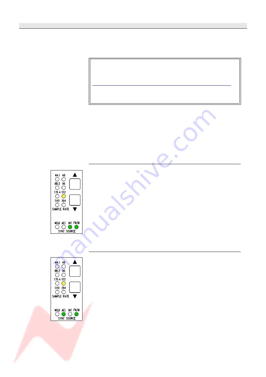
As in standalone mode, the green leds indicate the lock source selected, 
and the yellow leds indicate the sample rate (from 44.1kHz to 192kHz). 

Picture, left, the 4081 under FireWire control, set to Internal sync running at 
192kHz. 

AES/EBU lock in FireWire mode

Once AES/EBU sync is selected on the DAW application, the green AES led 

will illuminate. 

If the green led is flashing, it means that the AES/EBU source is running 
at a different sample rate to the 4081. 

 Change the sample rate of the 4081 from the DAW application until the 

green AES/EBU led is solid, or change the sample rate of the 
syncronisation source to match that of the 4081. 

The sample rate of the 4081 is indicated by the yellow leds.

The 4081 can lock to either of the AES/EBU inputs. 

Picture, left, shows the 4081 under FireWire control locked to a 192kHz AES source.

- 9 -

Summary of Contents for Neve 4081

Page 1: ...81 Quad Mic Preamp User Manual Issue 3 Firmware V2 0 or later The 4081 is a quad mic line pre amplifier based on the classic 1081 modules and provides both powerful control and the legendary Neve soun...

Page 2: ...ect The Power Cord Use Only Accessories Specified By The Manufacturer Unplug When Unused For Long Periods Of Time Refer All Servicing To Qualified Personnel Only No User Serviceable Parts Inside FAILU...

Page 3: ...Rack Reset All Racks 18 Checkboxes 18 Create Debug File 18 Auto Load Last Setup File On Startup 18 Auto Restore Previous Setup On Startup 18 Pro Tools Control Setup 20 AD DA FireWire Expansion Board...

Page 4: ...t The unit always powers up with all settings levels and states as they were at power down An optional Digital module provides a Firewire AES interface with four channels of A D and D A conversion to...

Page 5: ...rface and not the AES If a Firewire connection is not detected then the 4081 will presume the audio is coming in via the AES IN OUT 25 way D type connector The optional expansion module has 4 DA AD co...

Page 6: ...d unlit for LINE Swaps the incoming phase of the Mic or Line signal INS This selects the source for the A D in the FireWire expansion module if fitted When illuminated allows an external Insert Pre th...

Page 7: ...ring Again these can run at up to 192kHz true stereo single wire 192kHz operation Control of the sample frequency and syncronisation source in standalone mode is done entirely through the front panel...

Page 8: ...e when AES EBU sync is selected If the green led is flashing it means that the AES EBU source is running at a different sample rate to the 4081 Change the sample rate of the 4081 using the and buttons...

Page 9: ...puts to the DAC outputs as these are reserved for the FireWire Setting the Sync source in FireWire mode In FireWire mode selection of the sync source and sample rate is done entirely from the DAW appl...

Page 10: ...ce is running at a different sample rate to that selected on the 4081 Change the sample rate of the 4081 from the DAW application until the green AES EBU led is solid or change the sample rate of the...

Page 11: ...d to Once it has downloaded double click the file to run and install it The Windows operating system will be determined as will the correct driver for your system A Windows CMD screen will show the in...

Page 12: ...procedure will terminate here Click Next A summary of the software development will be shown Click Next Select the location to install the software to It is recommended you leave this set to the defa...

Page 13: ...ish to launch the programme at this point select Launch 4081 Remote Mic Pre Amp Controller option before clicking Finish and the programme will then open Click Finish The first time the software is op...

Page 14: ...ure is still the same At any point in the install you can return to the previous screen by click Back Before installing this software please connect your 4081 via USB and power the unit up Double clic...

Page 15: ...for you Click Continue Click Install to continue and the software will start to be installed Once installed a confirmation screen will report it has been installed successfully Click Close Once instal...

Page 16: ...nt panels will be updated with any changes made on screen If you wish to enable the metering on the Main Screen ensure the Enable Meters tickbox is checked If this is left unticked the only indication...

Page 17: ...version of firmware is displayed next to the first four units To test the ID of each unit click the relevant Test button This will flash all of the Phase buttons once on that particular unit and you...

Page 18: ...n all operational aspects this screen is identical to the full size screen except for Click or to step through the racks in numerical order the display will reflect which rack is being displayed and w...

Page 19: ...ve a mic suffix Load Preset Once selected opens a standard Windows Load dialogue so that the files created above can be loaded back to the units The settings are global ie there is nothing to set or s...

Page 20: ...his will appear either as an icon on the desktop or can be accessed from the Applications folder On the main page click Setup and the General screen will open At the top of the screen click MIDI In bo...

Page 21: ...tartup option will cause the last saved or last loaded system setup to be reloaded when the software is next started When controlling the 4081 from Pro Tools it is advisable to turn this option off On...

Page 22: ...r of pliers Fitting Instructions Ensure that the 4081 unit is powered down and remove the 48v power cable from the 4081 Remove the expansion blanking panel from the back of the 4081 and also the lid R...

Page 23: ...he FireWire board to the posts Connect the 2 pin power cable between J16 of the expansion board and the power distribution board mounted on the front panel of the unit as shown below The power connect...

Page 24: ...king the Setup button and then checking the version against each unit Where you have more than one unit connected via the USB RS485 chain it is important that all units are running the same versions o...

Page 25: ...as Insert Sends The Output is Post the Gain control Pin outs as above Power input 48 volts 8 pin connector This connector is polarised so can only be connected one way INS IN LINE OUT A 25 pin D sub c...

Page 26: ...X 2 3 1 screen 1 AES 1 contains data for channels 1 L and 2 R from the 4081 AES 2 contains data for channels 3 L and 4 R from the 4081 On the AES Ins Outs 25 way connector on the rear of the 4081 a nu...

Page 27: ...ld have a unique ID as shown left The procedure for setting these IDs is described on page 29 Cable Specification The RS 422 specification recommends 24AWG twisted pair cable with a shunt capacitance...

Page 28: ...creen 1 Male XLR 4 14 Line Out 4 hot 2 8 1 Line Out 4 cold 3 2 screen 1 Female XLR 1 12 Insert IN 1 hot 2 1 24 Insert IN 1 cold 3 25 screen 1 Female XLR 2 23 Insert IN 2 hot 2 2 10 Insert IN 2 cold 3...

Page 29: ...switch block labelled SW2 inside the unit with the front of the unit to the left this switch block is just above a white programming connector With this switch in the down position the unit will have...

Page 30: ...pe 1A 20mm x 5mm Location FS1 Mains Power The power supply is universal input type and therefore no mains operating voltage setting is required Technical Earth When switched on internally connects zer...

Page 31: ...4081 User Manual Issue 3 Dimensions single unit 31...

Page 32: ...eserve the right to alter specifications without notice but with due regard to all current legislation Disclaimer The information in this manual has been carefully checked and is believed to be accura...

Reviews: