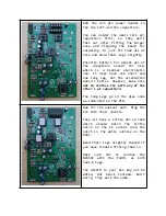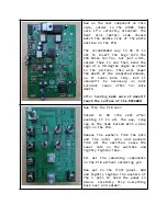
Add the 2x5 pin power header in
the top left and the capacitors.
You can solder the small (0.1 µF)
capacitors
first,
so
they
won’t
fall out after fitting the larger
ones and flipping the board for
soldering. Or just fit them all at
once and bend their legs slightly.
Polarity matters for almost all of
the
capacitors
except
for
C12,
which
is
a
bipolar
electrolytic
one. It does have one short and
one long leg, but the orientation
doesn’t matter. However, make sure
not to confuse C12 with any of the
other 1 µF capacitors!
The long legs go on the plus side
as indicated on the PCB.
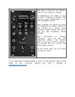
Now for the easiest part: Plug the
ICs into their sockets.
They all have a little dot on them
which
should
match
the
little
notch on the IC socket (and the
notch in the white outline on the
PCB).
Bend their legs slightly inward if
you have trouble fitting them in.
Make
sure
not
to
confuse
the
NE555P
with
the
TL072,
as
both
have 8 legs.
The H11F1M in your kit may not be
white,
but
black
instead.
Don’t
worry, they work the same.


