LB-EO Rev.
3
3
Configuration
3.1
Format configuration
The LB-EO can be configured in three different modes:
−
Automatic gain control (AGC mode)
−
Manually controlled gain using rotary switches (SW2 and SW3)
−
Sample AGC (automatically adjust gain and lock gain adjustment)
The configuration can either be set with a DIP switch or with the Flashlink GYDA Control
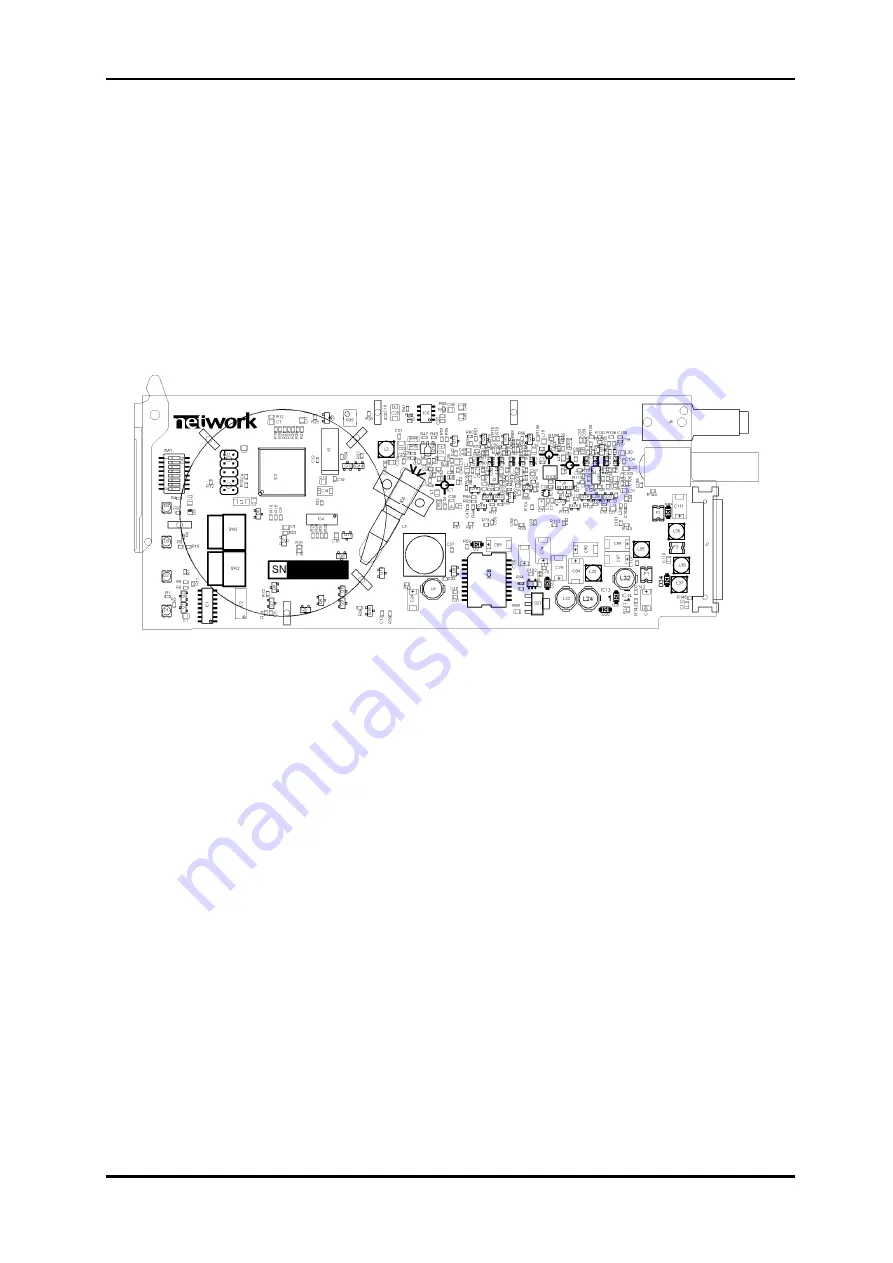
System. The layout of the Flashlink LB-EO is shown in the drawing below with the DIP switch
to the upper left position.
Figure 2: LB-EO board layout.
For setting the gain manually, use the rotary switches SW2 and SW3 situated near the
extractor handle. The two switches make a two digit number. SW3 is the tens and SW2 is
the ones. The number is gain in decibel (0-31dB). If larger number than 31 is set, the gain
will be 31. An ideal setting for the attenuator is LOS green and no light in LEVEL. Decrease
the number until LEVEL orange, and then increase the number one by one until LEVEL stops
lighting.
network-electronics.com | 6


