ADC-SDI-CC
Rev. 3
DATE: 23 July 2008
Network Electronics AS, P.O.Box 1020, N-3204 Sandefjord, Norway. Tel.: +47 33 48 99 99 – Fax: +47 33 48 99 98
E-mail: [email protected] – Web: http://www.network-electronics.com/
Technical specifications are subject to be changed without notice.
9
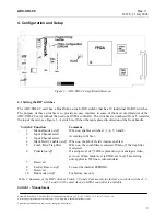
Switch 1 is the manual mode switch. If
on
, the ADC-SDI-CC may be operated with the switches. If
off
,
DA controller.
witch 1 in
on
position
ith switch 1
off
:
mode, switches 2, 3, 4, 5, 6 and 8 do not have any effect.
ith switch 1
on
:
e functionality of switches 2, 3, 4, 5 , 6 and 8 is as follows:
witches 2 and 3
tion. See
Table 2
.
F
e
sw
f
.
#3
#2
nnel Select
the ADC-SDI-CC is to be used with a GY
Factory setting is s
W
While in automatic
W
In manual mode, th
S
These two switches determine the input selec
actory s tting is
itch 2 and switch 3
of
Sw
Sw
Input Cha
0 0 CVBS
0 1 S-Video
1 0 YPbPr
1 1 RGBS
Table 2: Manual selection of video mode
Mark Field 1
-feature is enabled and the card inserts a marker on line x of each field
. This features gives improved encoding quality when used with an encoder like the DAC-SDI which
tting is switch 4 in
on
position.
witch 5 selects which filter to use when separating Luma from Chroma in CVBS. With switch 5
on
, the
off
, the chroma trap filter is selected.
tting is switch 5 in
on
position.
on
, the black level will
set to 7,5 IRE. With switch 6
off
, the black level will be 0 IRE. This switch only affects 525 lines
used in the USA and 0 IRE in Japan.
Factory setting is switch 6 in
on
position.
Switch 4
Switch 4 turns on/off the
Mark Field 1
-feature. With switch 4
off
the
Mark Field 1
-feature is disabled,
with switch 4
on
the
1
can use this feature.
Factory se
Switch 5
S
5-line comb filter is selected, with switch 5
Factory se
Switch 6
Switch 6 selects whether pedestal is present on the analogue video. With switch 6
be
video. Typically a black level of 7,5 IRE is


