background image

ADC-SDI-CC  


Rev. 3


DATE: 23 July 2008 


Network Electronics AS, P.O.Box 1020, N-3204 Sandefjord, Norway. Tel.: +47 33 48 99 99 – Fax: +47 33 48 99 98 
E-mail: [email protected] – Web: http://www.network-electronics.com/ 
 
Technical specifications are subject to be changed without notice. 


19


50


It is assumed that while the product is in normal use, any batteries associated with real-time clocks or battery-backed RAM will 
be replaced at the regular intervals. 

The EFUP relates only to the environmental impact of the product in normal use, it does not imply that the product will 

continue to be supported for 50 years.


Recycling information 

Network Electronics provides assistance to customers and recyclers through our web site 

http://www.network-electronics.com

. Please contact Network Electronics’ Customer Support for 

assistance with recycling if this site does not show the information you require.   

Where it is not possible to return the product to Network Electronics or its agents for recycling, the 
following general information may be of assistance: 

Before attempting disassembly, ensure the product is completely disconnected from power and signal 

connections. 

All major parts are marked or labelled to show their material content. 
Depending on the date of manufacture, this product may contain lead in solder. 

Some circuit boards may contain battery-backed memory devices. 

Summary of Contents for ADC-SDI-CC

Page 1: ...network electronics com Multi standard NTSC PAL YPbPr RGB Decoder Converter Component and Composite Analogue Video Converter Rev 3 Flashlink User Manual ADC SDI CC...

Page 2: ...istory The latest version is always available in pdf format on our web site http www network electronics com Current revision of this document is the uppermost in the table below Revision Replaces Dat...

Page 3: ...Configuration and Setup 8 4 1 Setting the DIP switches 8 4 2 Reset 10 5 Module status 11 5 1 GPI ALARM Module Status Outputs 11 5 2 Front Panel Status Monitoring 12 6 Interface with GYDA and RS 422 c...

Page 4: ...backplane module see Figure 2 on page 7 4 Power on After some seconds the ADC SDI CC will be running and the input detected All LED s will be green and the SDI output active If this is not the case p...

Page 5: ...se ratio for each input channel When used with the GYDA control system gain adjustments may be made to each analogue input Composite video decoding utilises a 5 line adaptive comb filter for both the...

Page 6: ...Hz or NTSC 525 60Hz Y C S video Connector BNC Impedance 75 ohm Signal level 1Vp p Return loss 40dB Component and RGB Input Signal rate 625 50Hz or 525 60Hz Signal type RGB without setup with separate...

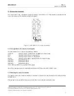
Page 7: ...connectors and signals The ADC SDI CC C1 connector module has 7 BNC s CVBS Y Analogue input CVBS SYNC for RGB or S Video Luma R Pr Analogue input Red or component Pr G Y Analogue input Green or compo...

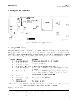
Page 8: ...nterface to some of the most used features of t A top of the card see Figure 3 h is off when Function Comment 1 Manual mode on off When on enables switches 2 3 4 5 6 and 8 2 Input Channel select 3 Inp...

Page 9: ...S 0 1 S Video 1 0 YPbPr 1 1 RGBS Table 2 Manual selection of video mode Mark Field 1 feature is enabled and the card inserts a marker on line x of each field This features gives improved encoding qual...

Page 10: ...ault values This is flagged by the Card State LED which starts to blink yellow 4 Power down 5 Turn switch 8 off If you want the DIP switches to be placed in the factory default position this is the ti...

Page 11: ...described on the next page The GYDA controller is described in a separate user manual This manual is available on our web site http www network electronics com 5 1 GPI ALARM Module Status Outputs Thes...

Page 12: ...n Figure 5 below Text not printed on the front panel Figure 5 Front panel indicator for ADC SDI CC The ADC SDI CC has 4 LED s each showing status information The position of the different LED s is sho...

Page 13: ...format to CVBS Svideo OK Set video format to S Video RGB OK Set video format to component RGB sync YPbPR OK Set video format to component YPbPr MarkF1 on OK Turn on the Mark Field 1 feature MarkF1 of...

Page 14: ...Locked to 625 lines 50 Hz Locked 60Hz Locked to 525 lines 60 Hz Not locked 50Hz Not locked previously locked to 50Hz Analogue input Not locked 60Hz Not locked previously locked to 60Hz Field 1 marking...

Page 15: ...tp www network electronics com Technical specifications are subject to be changed without notice 15 6 5 Mark Field 1 Pedestal and Comb commands Commands to turn on off the Mark Field 1 feature Pedesta...

Page 16: ...hout notice 16 General environmental requirements for Network flashlink equipment 1 The equipment will meet the guaranteed performance specification under the following environmental conditions Operat...

Page 17: ...m Web http www network electronics com Technical specifications are subject to be changed without notice 17 Product Warranty The warranty terms and conditions for the product s covered by this manual...

Page 18: ...eriod This is defined as the period of normal use before any hazardous material is released to the environment The guidance on how the EFUP is to be calculated is not finalised at the time of writing...

Page 19: ...be supported for 50 years Recycling information Network Electronics provides assistance to customers and recyclers through our web site http www network electronics com Please contact Network Electron...

Page 20: ...DEL NUMBER S ADC SDI CC DESCRIPTION Component and Composite Analogue Video Converter DIRECTIVES this equipment complies with LVD 73 23 EEC EMC 2004 108 EEC HARMONISED STANDARDS applied in order to ver...

Reviews: