


12
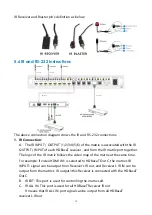
IR Receiver and Blaster pin
’
s definition as below:
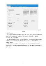
5.6
IR and RS-232 Instructions
The above connection diagram shows the IR and RS-232 connections:
1.
IR Connection:
A. The IR INPUT / OUTPUT (1/2/3/4/5/6) of the matrix is associated with the IR
OUTPUT / INPUT of each HDBaseT receiver , and form the IR matrix port together.
The logic of the IR matrix follows the video map of the matrix at the same time.
For example: if video HDMI IN1 is selected to HDBaseT Out C, the matrix's IR
INPUT1 signal can be output from Receiver's IR out, and Receiver's IR IN can be
output from the matrix's IR output1,this Receiver is connected with the HDBaseT
OutC.
B. IR EXT: This port is used for controlling the matrix self.
C. IR ALL IN: This port is used for all HDBaseT Receiver IR out
It means that IR ALL IN port signal can be output from all HDBaseT
receiver's IR out
Summary of Contents for ND-66-B70
Page 1: ...3 ND 66 B70 6 6 HDMI 18Gbps over HDBaseT Matrix with Audio Matrixing VER 2 1...
Page 14: ...1 6...
Page 15: ...1 7...
Page 16: ...1 8 7 Connection Diagram...


