background image


Chapter 2 Installation Guide 

2.1 Acquisition Check 

When users open the package of the device, it is necessary to check items according to packing list. 

Normally it should include the following items: 


NetUP Streamer HD v.3 


Power Cord 


HDMI cables 

If any item is missing or mismatching with the list above, please contact local dealer. 

2.2 Installation Preparation 

When users install device, please follow the below steps. The details of installation will be described at 

the rest part of this chapter. Users can also refer rear panel chart during the installation. 

The main content of this chapter including: 


Checking the possible device missing or damage during the transportation 


Preparing relevant environment for installation 


Installing Encoder 


Connecting signal cables 


Connecting communication port (if it is necessary) 

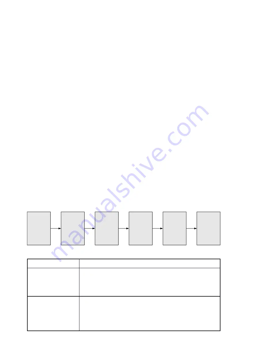
2.2.1 Device’s Installation Flow Chart is Illustrated as following


Connecting 

Grouding 

Wire and 

Power 

Cord

Acquisition 

Check

Fixing 

Device

Setting 

Parameter

Running 

Device

Connecting 
Signal Wire


2.2.2 Environment Requirement 

Item 

Requirement 

Machine Hall Space  

When user installs machine frame array in one machine hall, 
the distance between 2 rows of machine frames should be 
1.2~1.5m and the distance against wall should be no less than 
0.8m. 

Machine Hall Floor 

Electric Isolation, Dust Free 
Volume resistivity of ground anti-static material: 

1X10

7

~1X10

10

Grounding current limiting resistance: 1M 

(Floor bearing should be greater than 450Kg/

Summary of Contents for Streamer HD v3 8-24x

Page 1: ...NetUP Streamer HD v3 8 24x User manual 9 November 2022 15224 Alton rd Miami Beach 33140 FL USA info netup tv http netup tv...

Page 2: ...rinciple Chart Each Encoder Module 4 1 4 Specifications 4 1 5 Appearance and Illustration 5 Chapter 2 Installation Guide 7 2 1 Acquisition Check 7 2 2 Installation Preparation 7 2 3 Wire s Connection...

Page 3: ...al distribution systems such as cable TV digital head end digital TV broadcasting etc 1 2 Main Features 8 HDMI inputs with 8 SPTS and 1 MPTS output each encoder module max 24 HDMI inputs MPEG4 AVC H 2...

Page 4: ...ut 1920 1080_30P 1920 1080_25P 1280 720_30P 1280 720_25P 720 x 576_25P 720 x 480_30P Encoding MPEG 4 AVC H 264 Bit rate 1 13Mbps each channel Rate Control CBR VBR GOP Structure IP P P Frame adjustment...

Page 5: ...ower requirements AC 110V 10 50 60Hz AC 220 10 50 60Hz 1 5 Appearance and Illustration Front Panel Illustration 1U chassis three encoder modules illustration 1 2 3 1 Module 3 NMS and Data port and ind...

Page 6: ...Rear Panel Illustration 1 2 3 4 5 1 Grounding Pole 2 Power Switch and socket 3 Module 1 HDMI 1 8 4 Module 2 HDMI 9 16 5 Module 3 HDMI 17 24...

Page 7: ...e missing or damage during the transportation Preparing relevant environment for installation Installing Encoder Connecting signal cables Connecting communication port if it is necessary 2 2 1 Device...

Page 8: ...Therefore the system must follow this rule Coaxial cable s outer conductor and isolation layer should keep proper electric conducting with the metal housing of device Grounding conductor must adopt c...

Page 9: ...necting Grounding Wire When the device solely connects to protective ground it should adopt independent way say share the same ground with other devices When the device adopts united way the grounding...

Page 10: ...0 101 10 0 0 102 For model 24x 10 0 0 101 10 0 0 102 10 0 0 103 Connect the PC Personal Computer and the device with net cable and use ping command to confirm they are on the same network segment I G...

Page 11: ...king Enc CH 1 8 it will display the each encode channel information of the program from the HDMI input port as Figure 3 Figure 3 Click this button to apply the modified parameters Video and Audio Sett...

Page 12: ...3 supports TS to output in IP 8 SPTS format through the DATA port When users click IP Stream it will display the interface as Figure 4 where to set IP out parameters For Data 1000M GE port Figure 4 Cl...

Page 13: ...ption or QRcode Select program1 8 to apply the logo insertion or you can select all to apply all programs Click here to confirm the LOGO you selected Browse and select the Logo which has been created...

Page 14: ...TA parameters Figure 8 System Account Clicking Account it will display the screen as Figure 9 where to set the login account and password for the web NMS Both the current username and password are adm...

Page 15: ...Figure 9 System Configuration Clicking Configuration it will display the screen as Figure 10 where to save restore factory set backup load your configurations Figure 10...

Page 16: ...irmware it will display the screen as Figure 11 where to update firmware for the encoder Figure 11 System Date Time Clicking Date Time it will display the screen as Figure 12 where to set date and tim...

Page 17: ...System Log Clicking Log it will display the log interface as Figure 13 where to check or export the Kernel System log Figure 13...

Page 18: ...n off the device and unplug the power cord in the following cases The power cord or socket is damaged A liquid is splashed on the device A short circuit has occurred The device is in damp environment...

Reviews: