


39
SitePlayer Telnet User’s Manual
End Plate Description
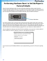
The SitePlayer Telnet system has two end plates which contain three connectors, an LED indicator and a
reset button. The Power Over Ethernet (POE) version of SitePlayer also has two LEDs on it’s RJ45 connector.
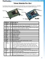
RS232C DB-9 Connector
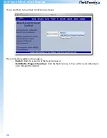
Recessed Reset Button
The Recessed Reset Button is used to reset SitePlayer to
its factory default state. See the
Performing Hardware
Reset to Set SitePlayer to Factory Defaults
section on
how to operate the button.
The DB-9 Connector is a male RS232C DTE connector.
This means that it is electrically identical to a PC serial
port connector.
Pin
Name
Direction
1
DCD
2
RX
3
TX
4
DTR
5
GND
6
DSR
7
RTS
8
CTS
9
RI
To SitePlayer
From SitePlayer
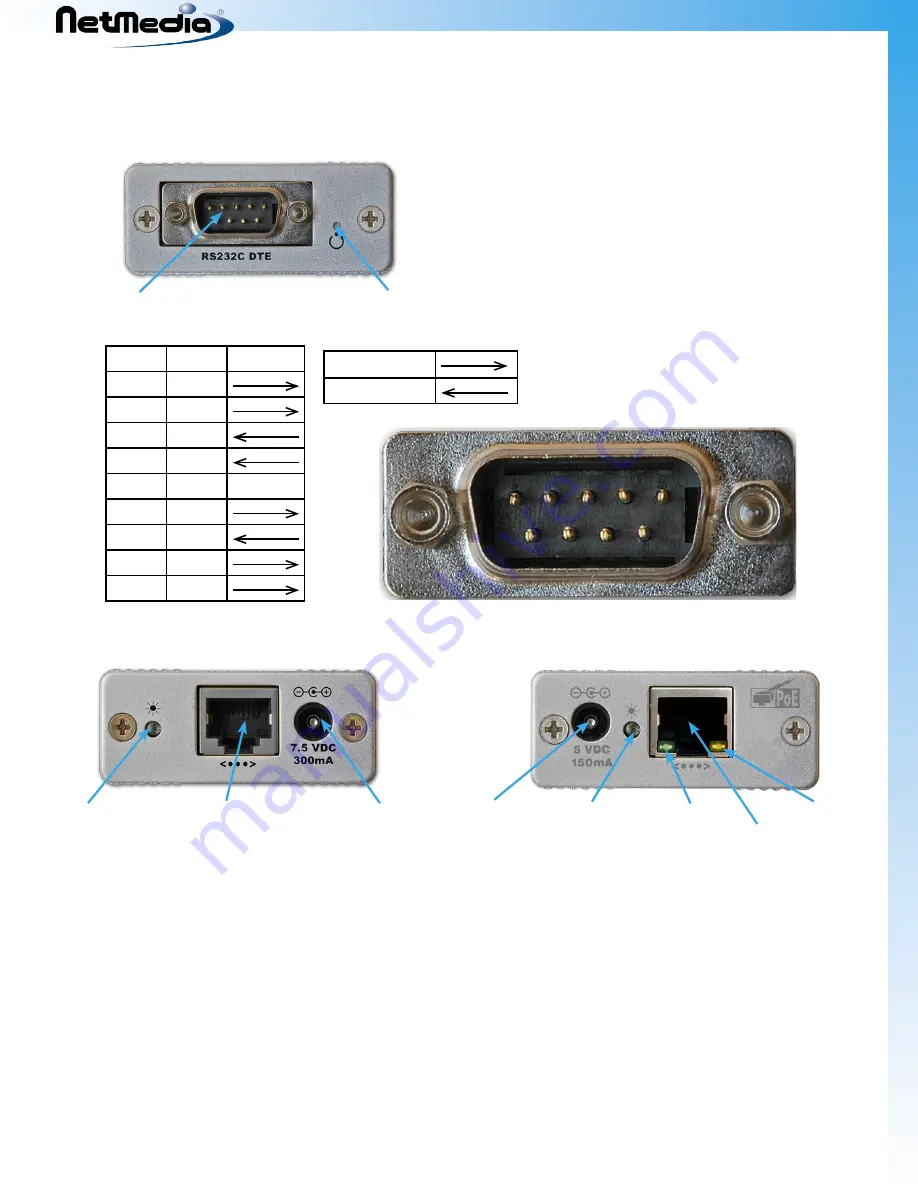
The Blue LED Indicator has multiple functions
During normal operation it indicates that the link is active. It stays constantly lit on an active link.
When SitePlayer is being reprogrammed the LED will flash indicate that the internal flash is being
erased and reprogrammed. This will happen when new Firmware or Website is software is loaded
or when the hardware reset button is pressed.
The Ethernet 10BaseT RJ45 Connector is used to connect to the Ethernet network. The POE version contains
a green link LED by the RJ45 connector which indicates that there is a valid link and also an orange Power
LED which indicates that Siteplayer has power (either POE or optional 5VDC).
The Power Connector label indicates the voltage that SitePlayer is rated for. The current rating on the Power
Label is the maximum power SitePlayer is rated for, although it typically consumes less than 150ma.
•
•
1
2
3
4
5
6
7
8
9
Blue LED Indicator
Ethernet 10BaseT RJ45 Connector
Power Connector
7.5VDC
Non-POE
Ethernet 10BaseT RJ45 Connector
Power Connector
(optional) 5VDC
Blue LED Indicator Green Link LED
Orange Power LED
POE
Summary of Contents for SitePlayer Telnet Series
Page 50: ...SitePlayer Telnet User s Manual 50 Telnet Carrier Schematic ...
Page 52: ......