


Chapter 4. Installation
|
23
GS752TXS Smart Switch Hardware Installation Guide
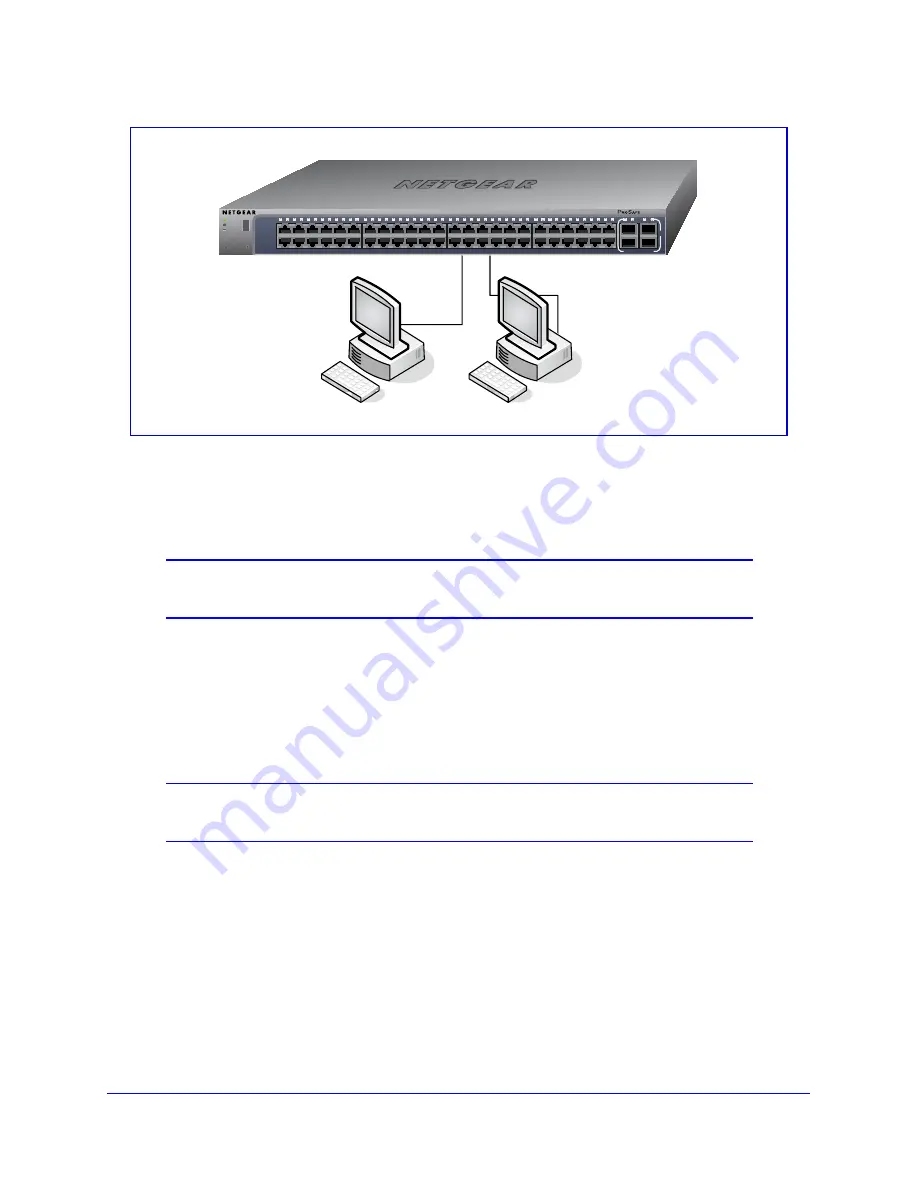
Figure 7. Connecting Devices to the Switch
Connect each PC to an RJ-45 network port on the Switch front panel (
Figure 7
). Use
Category 5 (Cat5) Unshielded Twisted-Pair (UTP) cable terminated with an RJ-45 connector
to make these connections.
Note:
Ethernet specifications limit the cable length between the switch and
the attached device to 100m (328 ft.).
Step 5: Installing an SFP Transceiver Module
The following procedure describes how to install an optional SFP(or SFP+) transceiver
module into one of the SFP ports of the switch.
Note:
Contact your NETGEAR sales office to buy these modules. If you do
not want to install an SFP module, skip this procedure.
To install an SFP transceiver, insert the transceiver into the SFP port. Press firmly on the
flange of the module to seat it securely into the connector. You can install up to three
additional Gigabit or 10 Gigabit Ethernet modules using this procedure.
`
`
Green=Link at 1G
Yellow=Link at 10/
100M
Power
Reset
ID
Fan
Stack
Master
Factory
Defaults
1
2
3
4
5
6
7
8
9
10
11
13
15
17
19
21
12
22
14
16
18
20
23
25
27
29
31
33
24
34
26
28
30
32
35
37
39
41
43
45
47
36
38
40
42
44
46
48
GS752TXS
50F
49F
Green=10G Link Yellow=1G
Blink=ACT
SFP
+
52F
51F
Link/Act Mode
—
Summary of Contents for Smart Switch GS752TXS
Page 5: ...GS752TXS Smart Switch Hardware Installation Guide Contents 5 ...
Page 11: ...Chapter 1 Introduction 11 GS752TXS Smart Switch Hardware Installation Guide ...
Page 17: ...Chapter 2 Physical Description 17 GS752TXS Smart Switch Hardware Installation Guide ...
Page 32: ...32 Appendix Technical Specifications GS752TXS Smart Switch Hardware Installation Guide ...


