background image

9

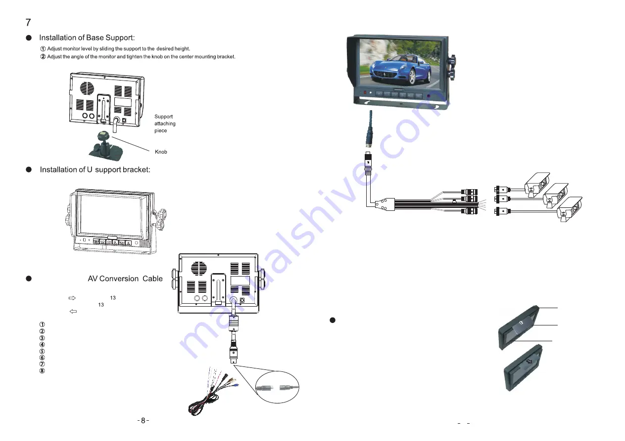
Black 13


pin male


White 4 pin male for Camera 1

.

Blue 4 pin male for Camera 2.

Brown 4 pin male for Camera 3.  

Single


red


wire


to positive power supply of DC:10-32V

.

Single


black


wire


to GND.

Single


white


wire


to


positive


power wire 


of


Camera 1

.    

Single


blue


wire to


positive power wire of  Camera 2.


Single


brown 


wire to


positive power wire of  Camera 3.


Blue

Brown

White

Blue 4 pin male


White 4 pin male


Brown 4 pin male


Black

Red


Black 13


pin female


Camera

Color LCD screen

Flush  mount

Detaching piece

Insert the detaching piece as indicated by the white

arrow. Press in and lift up, the monitor will be released 

from the flush mount.


Removing the Monitor:

Remove the monitor.

.  Basic Operation 

Connection of   


1

2

    -


Hold the cable , align the side of jack 

marked with      on the female  -pin 

connector  with the male  -pin connector 

marked with        then firmly plug together.

    White 4 pin male for Camera 1.     

       Blue 4 pin male for Camera 2.     

    Brown  4 pin male for Camera 3.


       Single red wire to power wire of DC : 10-32V.

       Single black wire to GND.

       Single white wire to positive power wire of the Camera 1. 

    Single blue wire to positive power wire of  Camera 2. 

       Single brown


wire to positive power wire of


Camera 3 .

1

2
3
4

5

6
7
8

Summary of Contents for NSM-7300AHD

Page 1: ...Operating Instructions NSM 7300AHD 7 HD Digital LCD Color Monitor Please read this manual thoroughly before operating the unit and keep it for future reference ...

Page 2: ...cleaning materials on this device 7 Do not place cables where they may be pinched or stepped on 8 Leave at least a 2 space between the monitor and walls cabinets or other objects to allow adequate air circulation around the unit 9 The monitor is not designed to be waterproof 1 Operating Precautions 1 The device may be powered by DC power 10V 32V eg 12V or 24V ACC 2 Observe polarity power s do not ...

Page 3: ... any changes or modifications not expressly approved in this manual could void your warrantee and neccessitate expensive repairs CAUTION This symbol is intended to alert the user not to waste electrical and electronic equipment Declaration of conformity This device complies with Part 15 of the FCC Rules Operation is subject to the following two conditions 1 This device may not cause harmful interf...

Page 4: ...er supply adapter cable IR Remote control Flush Mount optional Sun Shield Detaching Piece optional Angle Adjustment screws Brightness decrease Brightness increase Setting selection down Menu Remote control sensor Light level sensor Power switch Power indicator Digital Color LCD screen Loudspeaker CAM1 CAM2 CAM3 Selector Mounting bracket installation ...

Page 5: ...Selection Down More Brightness CH Setting Selection Up Press to select the upper setting Press to turn picture horizontally Horizontal Turning of Picture MENU Press to show menu CH Setting Selection Down Press to select the lower setting or to display the scale POWER Power Switch Press to turn on off the monitor Press to turn picture vertically Vertical Turning of Picture Press to decrease Brightn...

Page 6: ... piece Insert the detaching piece as indicated by the white arrow Press in and lift up the monitor will be released from the flush mount Removing the Monitor Remove the monitor Basic Operation Connection of 1 2 Hold the cable align the side of jack marked with on the female pin connector with the male pin connector marked with then firmly plug together White 4 pin male for Camera 1 Blue 4 pin male...

Page 7: ...ress LANGUAGE RESOLUTION BLUE BLACK AUTO DIM functions will display on the screen as illustrated below Press CH to select LANGUAGE 4 AUTO SCAN AUTO SCAN SCAN TIME CAM1 CAM2 CAM3 options display on the screen as illustrated below Press CH to select AUTO SCAN Press to select ON OFF Press CH to select SCAN TIME to adjust the scan time Press CH to select CAM1 to select ON OFF Press Press SYSTEM LANGUA...

Page 8: ...tiate request for repair Symptom Possible Causes Solutions No picture No picture Dark picture No color Upside down or lateral inverted picture No reversing function i e Picture Improper connection of automobile Use of un authorized power supply Power switch is on OFF position adapter Check whether AV cable is properly connected Check whether brightness and contrast are adjusted correctly Check whe...

Reviews: