


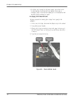

5. Use the Digital Volt-Ohm-Multimeter to measure the voltage. The
red leads are positive; the black leads are negative.
6. The voltage must be between 4.9V and 5.2V. Turn off the R450
DC circuit breaker.
If the voltage is above or below these values, it indicates that the
power supply is defective. Return the R450 DC to Neptune's
repair facility.
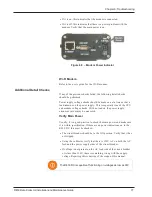
7. Reconnect CPU power.
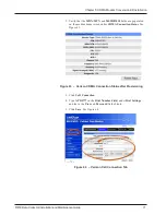
Verifying Radio Power
1. Turn off the circuit breaker if it is not already off.
2. Remove the BATT connector on the radio. The locking ring
unscrews.
3. Turn the circuit breaker back on.
4. On the power cable connector, measure the voltage across pins X
and Y as shown.
5. The voltage should be between 14.5V and 15.5V. If the voltage is
above or below these values, the power supply is defective and the
R450 DC should be returned to Neptune's repair facility.
6. If the voltage is within specifications, turn the circuit breaker off
and replace the connector. Make sure that the connector locking
ring is finger tight.
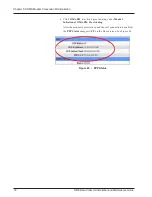
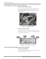
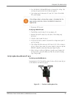
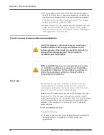
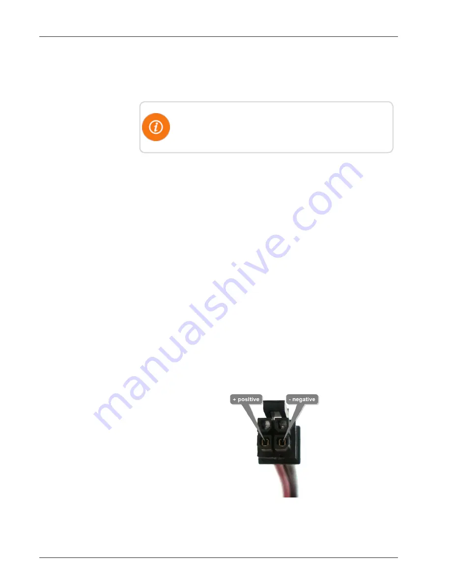
Verifying Backhaul Modem Power
Cal Amp LandCell Modem
Approximately 12.0 V should be present between the two pins shown
as illustrated in the following figure.
Figure 70 – Positive and Negative Pins
R450 Data Collector Installation and Maintenance Guide
79
Chapter 6: Troubleshooting
Summary of Contents for R450
Page 2: ......
Page 3: ...R450 Data Collector Installation and Maintenance Guide ...
Page 8: ...This page intentionally left blank ...
Page 143: ......


